How levers, pulleys and gears trade force for distance: the mechanical advantage MA=Fout/Fin, the work balance Win=Wout of an ideal machine, and the efficiency η of a real one.
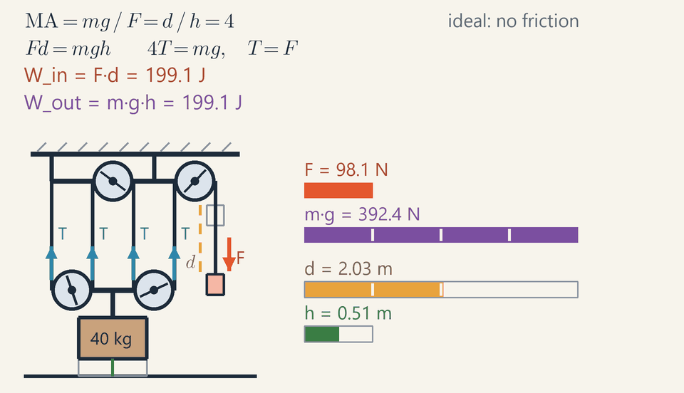
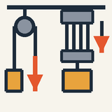
A block and tackle with four supporting strands lifts a 40 kg crate by 1 m while the free end of the rope is pulled 4 m: a quarter of the force, four times the distance.
Levers, pulleys, ramps and gears let a small force move a big load.
The price is distance: pull with a quarter of the force and you must pull four times as far.
In a pulley system, count the rope strands holding up the load: they share its weight.
A ramp is the same trick: a long, gentle slope needs a smaller push than lifting straight up.
No machine reduces the work (force × distance); friction makes real machines need a little more.
How can one person lift a car with a jack, or pull out a nail with a claw hammer? With simple machines: levers, pulleys, ramps, wheels and axles, screws and gears.
Step 1. A machine changes the force you need. A crowbar lets your hand push gently on the long end while the short end heaves up a heavy rock.
Step 2. Nothing comes free. Physicists measure work as force × distance, and a machine cannot hand out more work than you put in. So if it shrinks the force, it stretches the distance: push with a quarter of the force and you must push four times as far.
Step 3. Pulleys show this best. In the animation, one rope runs up and down between a fixed upper block and a lower block carrying the crate. Four strands, numbered 1 to 4, hold the lower block, so they share the crate's weight and your hand pulls with only a quarter of it: compare the short red "your pull" bar with the purple weight bar. But to raise the crate 1 m, each strand must shorten by 1 m, so 4 m of rope passes through your hand: the gold bar grows four times as fast as the green one.
Step 4. A ramp is the same trick: pushing a box up a long, gentle slope takes less force than lifting it straight up, but over a longer path.
Check yourself: a smooth ramp 4 m long rises 1 m. What push moves a 400 N crate up it? Answer: 100 N. Four times the distance means a quarter of the force.
Real machines do slightly worse than this ideal: friction in pulleys and bearings turns part of your effort into heat, so you always pull a little harder.
Intermediate
Key ideas
MA=Fout/Fin and IMA=din/dout; without friction Win=Wout, so MA=IMA.
Block and tackle: IMA=n, the number of strands holding the moving block; a single fixed pulley only turns the pull around.
Lever: FinLin=FoutLout. In the middle sits the fulcrum (class 1), the load (class 2) or the effort (class 3, MA<1).
Gears: torque is multiplied by Nout/Nin and rotation speed by Nin/Nout.
What a machine changes, and what it cannot
A hand pushes gently on the long end of a crowbar, and the short end heaves up a heavy rock. A simple machine takes the force you apply, the effort Fin, which moves through a distance din, and acts on a load with a force Fout through a distance dout; for a steady lift, Fout is the load's weight mg. Two pure numbers describe it: the mechanical advantage, measured on the real machine, and the ideal one, set by the geometry alone.
MA=FinFout
IMA=doutdin
A machine has no energy source of its own. Without friction the work put in equals the work delivered, Win=Wout, so Findin=Foutdout and MA=IMA: force is multiplied exactly as much as distance is divided. With friction, part of the input becomes heat Q, so Win=Wout+Q and the efficiency η=WinWout=IMAMA is less than 1. Friction changes the forces but not the distances, so the ratio of the works is the ratio of MA to IMA.
Pulleys: count the supporting strands
A pulley is a grooved wheel, a sheave, turning freely on an axle, so the tension T in the rope is the same on both sides. A single fixed pulley therefore only turns the pull around, with MA=1, although pulling down, helped by your own weight, is easier.
A block and tackle runs one rope up and down between a fixed upper block and a lower block that carries the load. If n strands hold up the moving block, they share the load, nT=mg, so the pull on the free end is F=T=mg/n. The geometry agrees: when the lower block rises by h, each strand shortens by h, and the spare rope, d=nh, comes out through your hand. Count only the strands attached to the moving block. Friction raises the pull by the factor 1/η: Block and tackle:d=nh,F=nηmg
Worked example: the hoist in the animation
The 40 kg crate weighs mg=40⋅9.81=392.4N, and the four strands numbered in the novice view hold the lower block, so n=4 and, in the ideal machine of this layer, T=F=nmg=4392.4=98.1N
Every blue T arrow on the strands has this length, and so does the red F arrow at the hand. The crate rises h=1.00m at 0.25 m/s while the hand pulls d=4⋅1.00=4.00m of rope at 1 m/s, along the dashed gold line. The two works are Win=Fd=98.1⋅4.00=392.4J Wout=mgh=392.4⋅1.00=392.4J
These are the final values on the two readouts, which climb together. The top line of the panel, MA=mg/F=d/h=4, sums it up: a quarter of the force, four times the distance, the same work.
Reading the rig: arrows, bars and the ceiling
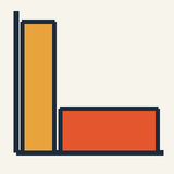
The red pull bar is a quarter of the purple weight bar, while the gold rope bar grows four times as fast as the green height bar. Think of each work as the area of a rectangle, force times distance: low and wide for the hand, tall and narrow for the crate, equal in area.
The arrows form a free-body diagram of the lower block: four T arrows pull it up and the weight pulls it down, so 4T=mg. The ceiling, however, carries more than the crate itself. The upper block is pulled down by all four strands and also by the free end, because you pull downward, so the ceiling must hold 5T=490.5N, which is mg+F.
Levers, gears and ramps
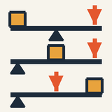
A lever is a rigid bar turning about a fixed point, the fulcrum. In a small turn each point moves in proportion to its distance from the fulcrum, so the arms Lin and Lout, both measured from the fulcrum, give IMA=Lin/Lout, and the torques balance: Lever:FinLin=FoutLout
What sits in the middle sets the class: the fulcrum in class 1 (crowbar, scissors), the load in class 2 (wheelbarrow, nutcracker; always MA>1), the effort in class 3 (tweezers, your forearm; always MA<1, trading force for speed and reach). A wheel and axle is a lever that keeps turning: a crank of radius R on a drum of radius r has IMA=R/r.
Gears are toothed wheels whose teeth all have the same size, so the number of teeth N is proportional to the radius: Gears:τinτout=ωoutωin=NinNout Here τ is the torque, in N·m, and ω the rate of rotation. In the expert inset an 8-tooth pinion drives a 24-tooth gear: a third of the speed, three times the torque.
A smooth ramp of length s rising h needs a push along it of only mgh/s, so IMA=s/h: a ramp 4 m long rising 1 m is the animation's tackle in another form.
Worked example: a geared hand winch
A building-site winch lifts a 150 kg pallet of tiles. Its 0.25 m crank turns a 10-tooth pinion, which drives a 40-tooth gear on the shaft of a drum of radius 0.050 m. The efficiency is 75 %. What force must you apply to the handle?
Crank and drum act as a wheel and axle with a factor 0.25/0.050=5, and the gears add 40/10=4. Ratios multiply along a chain of machines, so IMA=5⋅4=20, and MA=ηIMA=0.75⋅20=15 Fin=MAmg=15150⋅9.81=151471.5=98.1N
Check it with distances: one turn of the drum winds 2π⋅0.050=0.314m of rope and takes four turns of the crank, 4⋅2π⋅0.25=6.28m of hand travel, twenty times as far. A 1 m lift costs 98.1⋅20=1962J for 1471.5 J of output; the other 490.5 J warm the gears and bearings.
Common mistakes
Counting every length of rope. The fifth vertical length in the animation runs from the upper block to your hand and holds nothing up: n=4, and dividing by 5 would give 78.5 N.
Believing that a machine saves work. It saves force, never work: the real hoist of the expert view takes 490.5 J to deliver 392.4 J.
Measuring lever arms from the load. A 1.5 m crowbar on a fulcrum 0.10 m from its tip has arms of 1.40 m and 0.10 m, so MA=14, not 15.
Taking the losses as a share of the output. At η=0.80 the hoist needs 392.4/0.80=490.5J: the heat, 98.1 J, is a fifth of the input, not 20 % of the output.
Calling a machine with MA≤1 useless. A fixed pulley changes the direction of the pull, and tweezers trade force for fine movement.
Where you meet it
On a bicycle a 48-tooth chainring driving a 16-tooth sprocket turns the wheel three times per pedal turn: gears used the other way round, for speed. Your forearm is a class 3 lever: the biceps pulls about 4 cm from the elbow and the hand is 35 cm away, so holding a 50 N weight takes about 440 N of muscle force.
The hydraulic press of Fluid Pressure and Pascal's Principle is a machine whose advantage is a ratio of piston areas; transformers in Motors, Generators and Transformers trade voltage for current as gears trade torque for speed; and efficiency appears again, with a stricter limit, in First Law of Thermodynamics and Heat Engines.
Advanced
Key ideas
For a reversible machine Win=Wout, so a virtual displacement gives MA from geometry alone: Finδxin=Foutδxout.
η=Wout/Win=MA/IMA; the missing work, Win−Wout, becomes heat.
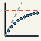
Per-sheave losses: nη=ηs(1−ηsn)/(1−ηs), so the actual MA can never exceed ηs/(1−ηs).
Ideal gears pass on power, τω=const; ratios multiply along a gear train.
If friction costs the same both ways, a self-locking machine (screw jack, worm gear) has η≤0.5.
Why every ideal machine obeys the same rule
Levers, pulleys, gears and ramps look nothing alike, yet they all trade force for distance in the same proportion. This section shows why, with an argument that uses no forces at all, only the fact that perpetual motion is impossible.
Call a machine reversible if, without friction, it runs backwards as readily as forwards: whatever it does one way, it can undo the other way. Now take two reversible machines. Each is driven by lowering the same 100 N weight by 1 m, and each uses that to lift the same load. The first lifts it by x1, the second by x2, and suppose that x2>x1.
Run the second machine forwards: the weight goes down 1 m and the load goes up x2. Then run the first machine backwards: it lowers the load by x1 and, in doing so, raises the 100 N weight back up by 1 m. The weight is where it started and both machines are as they were, yet the load hangs x2−x1 higher than before. Repeat the cycle and you raise the load for nothing, as often as you like.
Such perpetual motion is never observed, so the assumption was wrong: x2≤x1. The argument works just as well with the two machines swapped, which gives x1≤x2. Hence x1=x2: all reversible machines lift a given load equally high.
So one reversible machine is enough to find the rule for all of them, and a balanced lever is the simplest. Tip it slightly, and the weight lowered on one side times the height it falls equals the weight raised on the other side times the height it rises. A force times the distance moved along it is the work W, so for every reversible machine the input work equals the output work, Win=Wout.
A machine with friction is not reversible, and the same argument limits it. If it lifted the load higher than a reversible machine, running the reversible one backwards would again give something for nothing. So Wout≤Win, and the efficiency η=Wout/Win is at most 1. Sadi Carnot used the same reasoning in 1824 to show that no heat engine beats a reversible one working between the same two temperatures.
Virtual work: the advantage from geometry
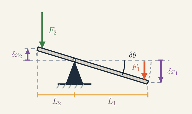
Figure 1. A lever in balance, tipped through a tiny angle δθ: the effort end, on the long arm L1, goes down by δx1 while the load end, on the short arm L2, goes up by δx2. Balance means F1δx1=F2δx2. Not to scale.Legend
F1
Effort pushing down on the end of the long arm: the input force.
N
F2
Load pressing down on the end of the short arm: the output force.
N
L1
Length of the effort arm, from the fulcrum to the effort.
m
L2
Length of the load arm, from the fulcrum to the load.
m
δθ
Tiny angle through which the lever is tipped, drawn large.
rad
δx1
Distance the effort end moves down: L1δθ.
m
δx2
Distance the load end moves up: L2δθ.
m
The rule Win=Wout turns a question about a machine's forces into a question about its geometry: how far each end moves. Figure 1 shows this for a lever in balance. The effort F1 pushes down on the end of the long arm L1, and the load F2 presses down on the end of the short arm L2; the subscripts 1 and 2 stand for "in" and "out".
Now imagine tipping the lever through a tiny angle δθ, drawn large in the figure so that it can be seen. A point at distance L from the fulcrum moves along an arc of length Lδθ, and for a tiny angle that arc is a short step straight up or down. Look at the two arrows at the ends of the lever: the effort end goes down by δx1=L1δθ and the load end goes up by δx2=L2δθ. Their ratio, δx1/δx2=L1/L2, is 2 in the picture and depends on the lengths of the arms alone.
Now apply the work rule. Because the lever is in balance, the movement can be made as slow as we like, so it gives the lever no kinetic energy; because the lever is reversible, none of the work turns into heat. All the work done by the effort therefore goes into raising the load: Finδxin=Foutδxout
The δx are virtual displacements: imagined rather than performed, and so small that the forces do not change while they happen. Only their ratio matters, and the constraints of the machine fix it, here the rigid lever turning about its fulcrum. For the lever the balance reads F1δx1=F2δx2. Put in the two displacements and δθ cancels, leaving the familiar torque balance F1L1=F2L2.
This is the principle of virtual work, and it gives a machine's advantage without a single free-body diagram. Two ratios describe any machine: the mechanical advantage MA=Fout/Fin, the factor by which it multiplies force, and the ideal mechanical advantage IMA=δxin/δxout, the ratio of the distances moved. Virtual work says that for a reversible machine the two are equal; for the lever both are L1/L2. With friction, η=Wout/Win=MA/IMA.
The tackle: a rope of fixed length
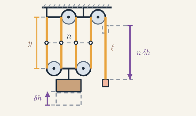
Figure 2. The lower block hangs y below the upper one on n strands, and ℓ is the rope from the upper block to the hand. Raising the load by δh shortens every strand by δh, so the hand comes down by nδh. Dashed boxes: where the crate and the hand were. Not to scale.Legend
y
Distance from the upper block to the lower one: the length of each supporting strand.
m
ℓ
Length of rope from the upper block down to the hand.
m
n
Number of strands holding up the lower block, here 4.
δh
Height through which the load is raised.
m
nδh
Distance the hand comes down: n times δh.
m
A block and tackle, the hoist of the animation, keeps its geometry in the rope. The rope does not stretch, and that single fact fixes how far the hand must pull. In Figure 2 the lower block, which carries the crate, hangs a distance y below the upper block on n=4 strands, each of length y, and ℓ is the length of rope from the upper block down to the hand.
The length of rope in the n strands plus the free end is the whole rope, so it stays the same: ny+ℓ=const,δℓ=−nδy
Now raise the load by δh, so that the lower block comes up and δy=−δh; the dashed boxes show where the crate and the hand were before. Each of the n strands is now shorter by δh. The rope they give up, nδh in all, goes to the free end, δℓ=nδh, so the hand comes down by nδh, the long arrow on the right.
Virtual work then gives the pull. The hand's force F acts over nδh while the weight mg rises by δh, so Fnδh=mgδh and F=mg/n: the IMA is n, the number of strands holding up the lower block. Dividing both distances by the time taken gives the speeds, vin=nvout: in the animation, 1 m/s at the hand and 0.25 m/s at the crate.
Gears and a slope by the same rule
The same reasoning handles machines that turn or slide. Two gears in mesh have teeth that touch and move together, so their rims share one speed: ωinrin=ωoutrout, where ω is the angular speed and r the radius. The teeth have the same spacing on both gears, so each radius is proportional to its number of teeth, and the speeds are in the inverse ratio of the tooth counts.
For a slope, take a block of mass M on a smooth incline of length s and height h, tied by a rope over a pulley at the top to a hanging mass M′. As M′ drops by s, it pulls the block the whole length of the slope and so raises it by h. The work balance M′gs=Mgh says the two balance when M′s=Mh: for a 4 m slope rising 1 m, a quarter of M is enough. Simon Stevin reached such results in 1586 another way: a closed loop of chain hung over a triangular block never starts turning by itself, which is again the impossibility of perpetual motion.
Losses, sheave by sheave
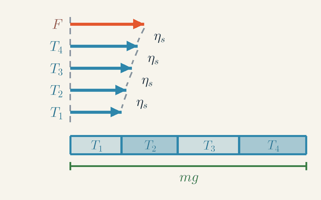
Figure 3. The rope of the animation's tackle laid out straight, all tensions to one scale. Each sheave passes on only a fraction ηs of the tension it receives, so the arrows shrink from F at the hand to T1 at the anchor, and the four strands together hold the load: T1+T2+T3+T4=mg.Legend
F
Pull of the hand on the free end of the rope.
N
T4
Tension in the strand next to the hand: ηsF.
N
T3
Tension in the second strand from the hand: ηs2F.
N
T2
Tension in the third strand from the hand: ηs3F.
N
T1
Tension in the fourth strand, tied to the upper block: ηs4F.
N
ηs
Fraction of the incoming tension that one sheave passes on; below 1 because of friction.
mg
Weight of the load, held by the four strands together.
N
So far every machine was reversible. Real pulleys have friction in their bearings, and the tensions in the rope show what it costs and where the cost appears. Figure 3 lays the rope of the animation's tackle out straight and draws every tension to one scale: the hand's pull F on top, then the four strands, from T4 next to the hand down to T1, the strand tied to the upper block.
The model is simple. Each sheave, the grooved wheel of a pulley, passes on only a fraction ηs of the tension it receives, a little less than 1, and the work lost warms its bearing. So each arrow in the figure is ηs times the one above it, as the ηs labels between them show.
Follow the rope back from the hand. It passes over one sheave before the first strand, so that strand carries T4=ηsF. One more sheave gives T3=ηs2F, and so on to the anchored strand with T1=ηsnF. The strands together hold up the load, which the bar at the bottom shows by laying the four arrows end to end against mg. Their sum is a geometric series: mg=F(ηs+ηs2+…+ηsn)=F1−ηsηs(1−ηsn)
Now bring in the efficiency η of the whole tackle. Its IMA is still n, so MA=nη and F=mg/(nη). Put that into the sum and the load cancels: nη=1−ηsηs(1−ηsn)
For the animation, η=0.80 and n=4 require ηs+ηs2+ηs3+ηs4=3.2, so ηs≈0.913. The 40 kg crate weighs 392.4 N, so the pull is F=392.4/3.2=122.6N. The strand tensions T1 to T4 are 85.1, 93.2, 102.2 and 111.9 N, and they add up to exactly 392.4 N: in the figure the blue arrows lengthen towards the hand, and the red F is the longest of all. The actual MA is nη=3.2 while the IMA is still 4, because friction changes the forces but not the geometry.
Reading the energy graph
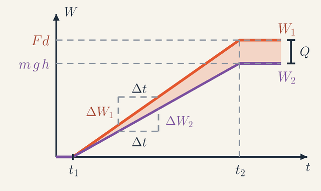
Figure 4. Work against time during the lift. The input W1 and the output W2 grow along straight lines from t1 to t2, then stay flat. In any stretch Δt they gain ΔW1 and ΔW2, in the ratio η; the shaded gap between them, which ends at Q, is the heat.Legend
t
Time since the start.
s
W
Work done so far.
J
W1
Input work: the hand's pull times the length of rope pulled in, Fd.
J
W2
Output work: the potential energy gained by the load, mgh.
J
Fd
Input work at the end of the lift.
J
mgh
Output work at the end of the lift.
J
t1
Instant the crate starts to rise.
s
t2
Instant the crate stops rising.
s
Δt
A short stretch of time.
s
ΔW1
Input work done during Δt.
J
ΔW2
Output work done during Δt.
J
Q
Heat made by friction in the sheaves: the final gap between the two works.
J
The work balance can also be watched as it happens. Figure 4 plots the two works against time during the lift, the subscripts 1 and 2 again standing for "in" and "out". The input work is W1=Win(t)=Fd(t), where d is the length of rope the hand has pulled in, and the output work is W2=Wout(t)=mgh(t), where h is the height the crate has risen.
Read the graph from left to right. Nothing happens before t1=0.4 s. From then on the crate rises at a constant speed, so both works grow along straight lines. At t2=4.4 s the lift ends: the hand has pulled in 4 m of rope and the crate is 1 m higher. The lines level off at Fd=490.5J and mgh=392.4J.
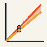
Each slope is a power, the rate of doing work. Look at the two small triangles: over the same stretch Δt the input line rises by ΔW1 and the output line by ΔW2. The hand pulls 122.6 N at 1 m/s, an input power of 122.6 W, while the crate gains potential energy at 392.4⋅0.25=98.1W. The ratio of the slopes is 0.80 at every instant, ΔW2/ΔW1=η, so the efficiency is also the ratio of output power to input power.
The shaded gap between the lines is the work lost to friction so far. It widens at 122.6−98.1=24.5W and ends at Q=490.5−392.4=98.1J, the bracket at the right of the figure and the value on the animation's heat readout. After t2 both lines are flat, because a machine that has stopped does no work, however hard it is held.
More strands, gear trains and self-locking
The loss model answers three practical questions: whether more strands always help, how losses add up along a chain of gears, and why some machines hold their load by themselves.
More strands do not help without limit. As n grows, ηsn→0, so the actual MA=ηs(1−ηsn)/(1−ηs) levels off at ηs/(1−ηs)≈10.5. Going from 4 to 8 strands raises it only from 3.2 to 5.4, while η falls from 0.80 to 0.68. Figure 3 shows the reason: each extra strand lies further from the hand and carries less tension than the one before.
Ideal gears pass on the power unchanged, τinωin=τoutωout, where τ is the torque: a gear that turns three times more slowly turns with three times the torque. In the animation's inset an 8-tooth pinion drives a 24-tooth gear; the pinion turns 270° while the gear turns 90°, and τ2=3τ1, with 1 for the pinion and 2 for the gear. Along a gear train the stage ratios multiply, two 1 : 3 stages giving 1 : 9, and so do the efficiencies. A good stage loses only a few per cent, so two stages at 0.98 still pass on 96 %.
A screw jack or a worm gear must hold its load when you let go; such a machine is called self-locking. To see when that happens, suppose friction costs the same heat Q whichever way the machine runs. Lifting then needs Win=Wout+Q. If the load tried to drive the machine backwards, the descending load would supply only Wout but would still have to pay Q; it cannot, and so stays put, if Wout≤Q. In terms of the lifting efficiency, that is η=Wout/(Wout+Q)≤0.5.
A car jack puts numbers on this. With a 0.20 m handle, one turn takes the hand round a circle of 2π⋅0.20=1.26m, while a screw advancing 2.0 mm per turn raises the car 0.0020 m, so IMA=2π⋅0.20/0.0020≈630. At η=0.30 the actual MA is about 190, and about 21 N at the handle lifts 4000 N. Since 0.30 is below one half, the car stays up when you let go.
Worked problem: lowering the crate
Run the animation's tackle backwards: lower the 40 kg crate by 1 m at a steady speed, with ηs=0.9127 at every sheave. How hard must the hand hold, and where does the energy go?
First, which way does friction act? The rope now runs from the hand into the tackle, and friction at each sheave still opposes its motion. So at each sheave the tension on the side the rope is moving towards must be the larger one: it is 1/ηs times the tension on the hand's side. The strand next to the hand carries F/ηs, the next F/ηs2, and so on up to F/ηs4 in the anchored strand. Together they still hold the load: mg=F(ηs1+ηs21+ηs31+ηs41)=5.052F F=5.052392.4=77.67N
These tensions are the four values of the lift in reverse order, from 111.9 N in the anchored strand down to 85.1 N next to the hand. The holding force is ηs5 times the lifting force, about 63 % of it: friction now helps the hand instead of fighting it.
Now the energy. The sinking crate releases mgh=392.4J. The hand lets out 4 m of rope while resisting with 77.67 N, so it absorbs 77.67⋅4.00=310.7J, and the sheaves turn the remaining 392.4−310.7=81.7J into heat.
If the bearings grip about as well at rest as in motion, any pull between 77.7 N and 122.6 N holds the crate still: below that range it sinks, above it it rises. Yet the holding force never reaches zero. With a lifting efficiency of 0.80, well above one half, the tackle is not self-locking, and if you let go the crate runs down.
Limits of validity
Every result above rests on idealisations: a massless rope that does not stretch, weightless sheaves, rigid levers, and slow, steady motion. Each can be relaxed, and the work balance shows what changes.
A 2.0 kg lower block is lifted with the crate, so it adds 19.6 N to the load and raises the ideal pull from 98.1 N to 103.0 N. Accelerating the crate upward at 0.5 m/s² needs a net upward force, nT=m(g+a), or 103.1 N per strand, and the extra work becomes kinetic energy rather than height. Real rope also stretches, and bearings have a loss that does not grow with the load, so a lightly loaded tackle does worse than a constant ηs predicts.
The work balance itself is the conservation of energy, and it has never been seen to fail. What changes at tiny scales is the smooth running.
A kinesin motor protein shows this. It walks along a filament inside a cell in 8 nm steps and stalls against a load of about 6 pN. It therefore does at most (6×10⁻¹²N)(8×10⁻⁹m)≈4.8×10⁻²⁰J of work per step, only about 11 times the thermal energy kT≈4.3×10⁻²¹J at body temperature, where k is Boltzmann's constant and T here the absolute temperature. Each step spends one ATP molecule, worth about twice that work, and random thermal kicks are a large part of the motion. At this scale the balance holds only on average, and the Second Law decides which way the machine can run.
Where this leads
Virtual work is a shortcut to the torque balances of Static Equilibrium and Levers, and Rotational Dynamics and Torque supplies the torque and the power P=τω that a gear pair passes on. The hydraulic press of Fluid Pressure and Pascal's Principle has an ideal advantage equal to a ratio of areas: 100 for pistons of 2 cm and 20 cm diameter. Transformers, in Motors, Generators and Transformers, multiply voltage by their turns ratio and divide current by it, passing on power as gears do. Rope stretch belongs to Elasticity: Hooke's Law, Stress and Strain. The reversible-machine argument returns in First Law of Thermodynamics and Heat Engines and The Second Law of Thermodynamics and Entropy, where it caps the efficiency of every heat engine.
Key formulas
Mechanical advantage
MA=FinFout
The mechanical advantage says how many times the machine multiplies the force you apply: the force it exerts on the load divided by your effort. It is measured on the real machine, so it already includes the losses to friction. A value below 1 is not a failure: it means that the machine trades force for speed or reach, as tweezers and your forearm do.
Symbols
MA
mechanical advantage
Fout
force exerted on the load (its weight mg for a steady lift)
N
Fin
effort, the force applied to the machine
N
When it holds: Defined for any machine. While the load accelerates, part of the force goes into speeding it up, and at rest friction can hold the load with a whole range of pulls, so measure the advantage with the load moving steadily.
Example: The real hoist of the animation: MA=392.4/122.6=3.2.
Ideal mechanical advantage
IMA=doutdin
The distance the effort moves divided by the distance the load moves. It depends only on the geometry (how many strands, how long the lever arms, how many teeth), so it can be read off a drawing. Without friction the work balance Findin=Foutdout makes it equal to the mechanical advantage.
Symbols
IMA
ideal mechanical advantage
din
distance moved by the effort
m
dout
distance moved by the load
m
When it holds: Holds for any machine whose parts keep their shape: inextensible rope, rigid levers, meshing teeth. A stretching rope or a slipping belt changes the ratio; friction does not.
Example: The animation's tackle: the hand pulls 4 m of rope while the crate rises 1 m, so IMA=4/1=4.
Efficiency
η=WinWout=IMAMA
The efficiency is the share of the input work that reaches the load; the rest, Win−Wout, becomes heat in bearings, rope and teeth. Because the distances are fixed by the geometry, dividing the works is the same as dividing MA by IMA. It is often quoted as a percentage.
Symbols
η
efficiency
Wout
useful work done on the load
J
Win
work done by the effort
J
MA
mechanical advantage
IMA
ideal mechanical advantage
When it holds: Between 0 and 1 for any machine without its own energy source; equal to 1 only for an ideal, reversible machine. If friction costs the same both ways, a self-locking machine has η≤0.5.
Example: The animation's real hoist: η=392.4/490.5=3.2/4=0.80.
Law of the lever
Lever:FinLin=FoutLout
Torques about the fulcrum balance: each force times its lever arm, the perpendicular distance from the fulcrum to the force's line of action. Turning the lever through a small angle moves each point in proportion to its arm, so the work balance gives the same rule and IMA=Lin/Lout. Measure both arms from the fulcrum, never from the load.
Symbols
Fin
effort
N
Lin
effort arm, from the fulcrum to the line of the effort
m
Fout
force on the load
N
Lout
load arm, from the fulcrum to the line of the load
m
When it holds: For a rigid lever in balance or turning slowly, with its own weight neglected or added as a further torque about the fulcrum. Friction at the fulcrum is usually tiny.
Example: A 1.5 m crowbar with its fulcrum 0.10 m from the tip: MA=1.40/0.10=14, so a 50 N push holds 700 N.
Block and tackle
Block and tackle:d=nh,F=nηmg
When the moving block rises by h, each of the n strands holding it shortens by h, so a length nh of rope passes through your hand. Ideally every strand carries the same tension, equal to the pull F, and nF=mg; friction raises the pull by the factor 1/η. Count only the strands attached to the moving block.
Symbols
d
length of rope pulled at the free end
m
n
number of strands supporting the moving block
h
height the load rises
m
F
pull on the free end of the rope
N
m
mass of the load
kg
g
free-fall acceleration, 9.81 m/s²
m/s2
η
overall efficiency of the tackle
When it holds: For a steady lift with inextensible rope and the moving block's own mass neglected (add it to the load otherwise). If the free end leaves the moving block and is pulled in the direction of the lift, it counts as a strand.
Example: The animation: d=4⋅1=4m and F=392.4/(4⋅0.80)=122.6N, or 98.1 N without friction.
Gear ratio
Gears:τinτout=ωoutωin=NinNout
Teeth in contact move together, and the teeth of both gears have the same size, so each gear's radius is proportional to its number of teeth and the rotation rate is divided by Nout/Nin. Ideal gears pass on the power τω, so the torque grows by the same factor as the rotation slows.
Symbols
τout
torque delivered by the driven gear
N⋅m
τin
torque applied to the driving gear
N⋅m
ωin
angular speed of the driving gear
rad/s
ωout
angular speed of the driven gear
rad/s
Nout
number of teeth on the driven gear
Nin
number of teeth on the driving gear
When it holds: The speed ratio is exact for meshing teeth, which cannot slip; the torque ratio assumes no friction, so real gears deliver a few per cent less torque. Along a gear train the ratios of the stages multiply.
Example: The inset: an 8-tooth pinion drives a 24-tooth gear, so ωout=ωin/3 and τout=3τin.
Advantage of a tackle with sheave losses
nη=1−ηsηs(1−ηsn)
If each sheave passes on a fraction ηs of the tension it receives, the strands carry ηsF, ηs2F, … ηsnF, counting from the hand. Their sum, a geometric series, must equal the load mg=nηF, which gives the formula. As n grows, the actual advantage nη levels off at ηs/(1−ηs): each extra strand adds less than the one before.
Symbols
n
number of supporting strands, one sheave each
η
overall efficiency of the tackle
ηs
efficiency of one sheave
When it holds: A model for a steady lift: it assumes the same fractional loss at every sheave. Real bearings also have a loss that does not grow with the load, which matters for light loads.
Example: The animation: n=4 and η=0.80 give nη=3.2, which needs ηs≈0.913; the limit would be 0.913/0.087≈10.5.
Glossary
Simple machine
A device with no energy source of its own that changes the size or the direction of a force by means of a rigid bar, a wheel, a rope or a slope. The classical six are the lever, the wheel and axle, the pulley, the inclined plane, the wedge and the screw; gears are toothed wheels and axles.
Effort and load
The effort is the force you apply to a machine; the load is the force the machine works against, often a weight. In the animation the effort is the pull on the rope and the load is the crate's weight, 392.4 N.
Mechanical advantage
How many times a machine multiplies the effort, MA=Fout/Fin, measured on the real machine with its friction. The animation's tackle has MA=4 when ideal and 3.2 with friction.
Ideal mechanical advantage
The ratio of the distances moved by the effort and by the load, IMA=din/dout, fixed by the geometry alone. Friction lowers MA but leaves IMA unchanged, so IMA is the advantage the machine would have without friction.
Efficiency
The fraction of the input work that reaches the load, η=Wout/Win=MA/IMA. It is below 1 in every real machine; the missing work becomes heat.
Work balance
In an ideal machine the work put in equals the work delivered, Findin=Foutdout: what is gained in force is lost in distance. It is the conservation of energy applied to machines, sometimes called the golden rule of mechanics.
Reversible machine
An ideal, frictionless machine that runs backwards as easily as forwards. No machine can lift a load higher than a reversible one for the same input work, and all reversible machines lift it to the same height.
Principle of virtual work
For a system in balance, the works done by all the forces in any tiny imagined displacement that the constraints allow add up to zero. It gives the advantage of a machine from its geometry alone, without resolving forces.
Lever classes
A lever is a rigid bar turning about a fixed point, the fulcrum. In class 1 the fulcrum is in the middle (crowbar), in class 2 the load (wheelbarrow), in class 3 the effort (tweezers, forearm), so a class 3 lever always has MA<1.
Block and tackle
Two blocks of pulleys with one rope running between them: the upper block is fixed and the lower one carries the load. Its ideal mechanical advantage is the number n of strands holding the moving block; a single fixed pulley has n=1 and only changes the direction of the pull.
Gear ratio
The number of teeth on the driven gear divided by the number on the driving gear, Nout/Nin. The rotation rate of the driven gear is divided by this ratio and, without friction, its torque is multiplied by it; along a gear train the ratios multiply.
Self-locking machine
A machine that the load cannot drive backwards, such as a screw jack or a worm gear, so it holds the load when you let go. If friction costs the same work in both directions, this requires η≤0.5.
Quantities
F
Effort (pull on the rope)
N
The force applied to the machine; in a block and tackle, the pull on the free end of the rope. Written Fin in the general ratios: 98.1 N in the ideal animation, 122.6 N with friction.
T
Rope tension
N
The pull that a rope strand exerts at each of its ends. In an ideal tackle every strand carries the same tension, T=F; with friction it falls from sheave to sheave away from the hand.
n
Number of supporting strands
How many rope strands hold up the moving block: the ideal mechanical advantage of a block and tackle. A free end leaving the fixed block does not count.
h
Height of lift
m
How far the load rises, the output distance dout of a hoist; 1 m in the animation.
d
Length of rope pulled
m
The rope that passes through the hand, the effort's distance din; d=nh for a block and tackle, 4 m in the animation.
W
Work
J
Force times the distance moved along it. The effort does Win=Fd on the machine, and the machine does Wout=mgh on the load.
η
Efficiency
The ratio Wout/Win, between 0 and 1, often given as a percentage: 0.80 for the real hoist of the animation.
Q
Heat produced by friction
J
The work lost in the machine, Win−Wout, which warms bearings, rope and teeth; 98.1 J for the animation's 1 m lift.
ηs
Efficiency of one sheave
The fraction of the rope tension that a single sheave passes on to the next strand; about 0.913 in the animation.
τ
Torque
N⋅m
The turning effect of a force about an axis, force times lever arm. A gear pair multiplies it by Nout/Nin while dividing the angular speed ω by the same factor.
ω
Angular speed
rad/s
How fast a gear turns. In the inset the 24-tooth gear turns at a third of the pinion's rate.
N
Number of teeth
The teeth on a gear, proportional to its radius: 8 and 24 in the inset.
Quiz
Beginner A pulley system like the one in the animation lets you lift a crate while pulling with only a quarter of its weight. What is the catch?
The crate gets lighter while it hangs from the pulleys
You must pull four times as much rope as the height the crate rises
The crate rises four times faster than your hand moves
It only works for loads lighter than you are
Show answer
Answer: B. You must pull four times as much rope as the height the crate rises
Four strands share the load, so each carries a quarter of the weight. But each strand must shorten by the height gained, so 4 m of rope passes through your hand for every 1 m of lift. Force × distance stays the same. Your hand therefore moves four times as fast as the crate, not the other way round.
Beginner Compared with lifting a load straight up by hand, what stays the same when you use an ideal (frictionless) simple machine?
The force you need
The distance your hands move
How fast your hands move
The work you do: force × distance
Show answer
Answer: D. The work you do: force × distance
A machine trades force for distance: less force means more distance, and the other way round. Their product, the work, is unchanged in an ideal machine and a little larger in a real one because of friction.
Beginner A small gear with 10 teeth drives a large gear with 30 teeth. How does the large gear turn?
Three times more slowly, but with three times the turning force
Three times faster, and with three times the turning force
At the same speed, because the teeth are locked together
Three times faster, but with a third of the turning force
Show answer
Answer: A. Three times more slowly, but with three times the turning force
The small gear has to turn three times to push all 30 teeth of the large gear past it once. Like a lever, the large gear trades speed for turning force: a third of the speed, three times the turning force (ignoring friction).
Intermediate A block and tackle has 3 rope strands supporting the moving block. Ignoring friction and the mass of the pulleys, what pull lifts a 900 N load at constant speed?
900 N
450 N
300 N
2700 N
Show answer
Answer: C. 300 N
The three strands share the load, and each carries the rope tension F, so 3·F = 900 N and F = 300 N. Only strands attached to the moving block count; 450 N would be the answer for two strands.
Intermediate A wheelbarrow carries an 800 N load whose weight acts 0.30 m from the wheel's axle. You lift the handles 1.20 m from the axle. Ignoring the barrow's own weight, what upward force do you need?
3200 N
200 N
800 N
267 N
Show answer
Answer: B. 200 N
The axle is the fulcrum of a class 2 lever. Torques balance: F × 1.20 m = 800 N × 0.30 m, so F = 200 N and MA = 1.20 ÷ 0.30 = 4. 267 N comes from wrongly measuring your arm from the load (0.90 m) instead of from the fulcrum.
Intermediate A single pulley fixed at the top of a flagpole is used to raise a 50 N flag. Ignoring friction, what does the pulley do?
It halves the force: you pull with 25 N
It halves the length of rope you have to pull
It reduces the work needed to raise the flag
It lets you pull down instead of up, still with 50 N
Show answer
Answer: D. It lets you pull down instead of up, still with 50 N
Only one strand holds the flag, so the rope tension equals its weight: MA = 1. A fixed pulley is still useful because pulling down is easier and you stay on the ground. To gain force you need a movable pulley, held by two strands.
Advanced A block and tackle with 4 supporting strands and an overall efficiency of 80 % lifts a 400 N load by 2.0 m. How much energy is turned into heat?
200 J
160 J
1000 J
0 J, because the load moves at constant speed
Show answer
Answer: A. 200 J
W_out = 400 N × 2.0 m = 800 J and W_in = W_out ÷ η = 800 ÷ 0.80 = 1000 J, so Q = 1000 − 800 = 200 J. Taking 20 % of W_out (160 J) is the usual slip: the losses are 20 % of the input.
Advanced Each sheave of a block and tackle passes on 90 % of the rope tension it receives. What happens to the actual mechanical advantage as more and more strands are added?
It keeps growing in proportion to n, as 0.9·n
It stays equal to 0.9 whatever n is
It levels off and can never exceed 9
It falls below 1 once there are more than about 10 strands
Show answer
Answer: C. It levels off and can never exceed 9
The strands carry F·(0.9 + 0.9² + … + 0.9ⁿ) = F·0.9·(1 − 0.9ⁿ)/(1 − 0.9). As n grows this tends to 0.9/0.1 = 9 times F: each extra strand adds less advantage than the one before.
 Physics Tutor