What an electric current I really is, why the electrons crawl at a drift speed vd while the signal races, and how a wire's material, length and thickness set its resistance, R=ρL/A.
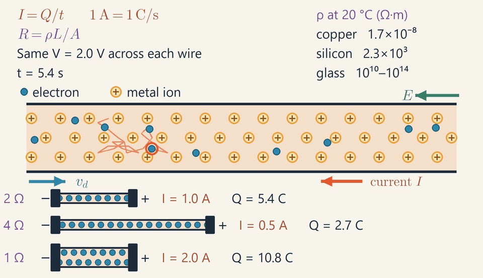
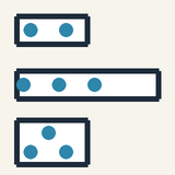
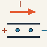
Inside a metal wire, electrons zigzag between the ions while drifting slowly along it; below, the same voltage drives half the current through a wire twice as long and twice the current through one with twice the cross-section.
An electric current is a flow of charge; in a metal wire, the moving charges are free electrons.
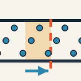
Current is measured in amperes: 1 A is one coulomb per second, so 10 C passing in 5 s make 2 A.
Electrons zigzag and bump into the metal ions, drifting only slowly; the bumps are the resistance and turn energy into heat.
With the same battery, a longer wire carries less current and a thicker wire carries more.
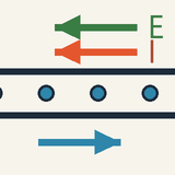
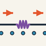
By convention current flows from + to −; the electrons themselves drift the other way, from − to +.
An electric current is simply moving electric charge.
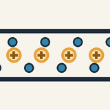
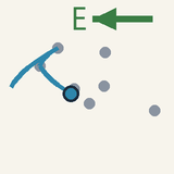
Step 1: what moves. In a metal, each atom lets go of one or two outer electrons, which wander freely between the atoms left behind (the ions). The magnified wire in the animation shows this crowd: yellow ions marked + in neat rows, blue electrons darting between them.
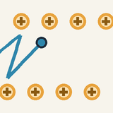
Step 2: the push. With no battery, the electrons rush about at random and get nowhere on average. Connect a battery and they all get a gentle push the same way: they still zigzag and bump into ions, but they also creep slowly along the wire. Follow the ringed electron: a tangled path, yet it works its way to the right.
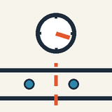
Step 3: counting. Current is measured in amperes. One ampere means one coulomb of charge, about six billion billion electrons, passing a point every second. If 10 coulombs pass in 5 seconds, the current is 10÷5=2A.
Step 4: which way. By an old convention, current is said to flow from the + end to the − end. Electrons are negative, so they actually drift the other way, from − to +.
Step 5: resistance. The bumps hold the electrons back and hand energy to the ions, which jiggle harder: the wire warms up. With the same battery, a wire twice as long lets through half the current; a wire twice as thick lets through twice as much. Metals conduct easily; glass and plastic hardly at all.
Electrons crawl slower than a snail, yet a lamp lights the instant you flip the switch: the wire is already full of electrons, and the push travels along it almost at the speed of light.
Check yourself: 30 coulombs pass in 10 seconds. What is the current? (Answer: 3 A.)
Intermediate
Key ideas
Current is charge per unit time: I=Q/t, and 1A=1C/s≈6.2×1018 electrons per second.
Conventional current points from + to −, along E; electrons drift the opposite way.
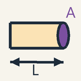
R=V/I in ohms; for a uniform wire R=ρL/A: double L doubles R, double A halves it.
Resistivity spans over 20 powers of ten: 1.7×10⁻⁸Ωm for copper, about 103 for silicon, 1010 and more for glass.
Current is not used up along a wire, and drift is slow: about 0.07 mm/s for 1 A in 1 mm² of copper.
What flows, and which way
A metal wire carrying no current is already full of moving charges. In a metal each atom releases one or a few outer electrons, which wander freely between the positive ions fixed in the crystal lattice. In salt water and batteries the carriers are ions. The current is the charge that crosses a cross-section of the conductor per unit time: I=tQ
The unit is the ampere, 1A=1C/s. An electron carries e=1.602×10⁻¹⁹C, so one ampere means 1/e≈6.2×1018 electrons crossing every second.
Conventional current points the way positive charge would move: from + to − through the outside circuit, along the electric field E inside the wire. Electrons are negative, so they drift the other way. In the animation the green E arrow and the red-orange current arrow I point left, while the blue drift velocity vd points right: negative charge moving right carries the same current as positive charge moving left.
Ohm's law and the current–voltage graph
The push that keeps charge flowing is the voltage V across the component, the energy each coulomb gives up between its ends (see Electric Field and Potential); in a uniform wire of length L it sets up a field E=V/L. Resistance compares the push with the flow: R=IV
Its unit is the ohm, 1Ω=1V/A. For a metal at a fixed temperature the current is proportional to the voltage, so R is a constant: this is Ohm's law, and a graph of I against V is a straight line through the origin with slope 1/R. A lamp filament's line bends over as it heats, its resistance growing more than tenfold, and a diode conducts one way only: V/I still defines their resistance at each point, but it is not a constant.
What sets the resistance of a wire
Picture a wire as segments in a row and as lanes side by side. Every extra metre is one more stretch to push the current through, so R grows in proportion to the length L; every extra square millimetre opens another lane, so R falls in inverse proportion to the area A. The material enters through its resistivity ρ: R=AρL
Resistivity, in ohm metres (Ω·m), is the resistance of a piece 1 m long with a cross-section of 1 m². The table in the animation shows its range: 1.7×10⁻⁸Ωm for copper, a conductor, 2.3×10³Ωm for pure silicon, a semiconductor, and 1010 to 1014Ωm for glass, an insulator: more than twenty powers of ten. The heating alloy nichrome has about 1.1×10⁻⁶Ωm.
In a metal ρ also rises with temperature, roughly as ρ(T)≈ρ0(1+αΔT), with ρ0 the value at 20 °C and ΔT the rise above it. For copper α=3.9×10⁻³K−1, about 0.4 % per kelvin. In a semiconductor ρ falls instead, because heat frees more carriers.
Worked example: the three wires in the animation
The three wires in the animation share the same 2.0 V. Suppose the top one, the reference wire, is nichrome 1.0 m long with a cross-section of 0.55mm2=0.55×10⁻⁶m2, about 0.84 mm across. Then R=AρL=0.55×10−61.1×10−6⋅1.0=2.0Ω I=RV=2.02.0=1.0A
These are the 2 Ω and 1.0 A printed beside it. Each blue dot stands for one coulomb, so one dot leaves the wire every second, and over the 12 s loop its counter climbs steadily to Q=It=1.0⋅12=12C, about 7.5×10¹⁹ electrons.
The middle wire is twice as long: R=4.0Ω, I=0.50A, and its counter reaches 6 C. The same 2.0 V is spread over 2.0 m, so the field halves to 1.0 V/m and its dots move half as fast. The bottom wire has twice the cross-section: R=1.0Ω, I=2.0A, 24 C after 12 s; its field is unchanged, so its dots move as fast as in the reference wire, but in two lanes.
How fast the electrons drift
Now count the carriers. With n carriers per cubic metre, each of charge q and drifting at speed vd, every carrier within a distance vdt upstream of a cross-section gets through it in a time t: a volume Avdt holding nAvdt carriers. Their charge divided by t is the current: I=nAvdq
Copper has about one free electron per atom, n=8.5×1028m−3. For 1 A in a wire of 1 mm², vd=nAeI=8.5×1028⋅10−6⋅1.602×10−191.0≈7.3×10⁻⁵m/s about 0.07 mm/s, or 26 cm per hour.
Yet the electrons dart about at some 1.6 million m/s; the drift is a tiny bias on that random motion. The ringed electron in the magnified wire shows both, a quick zigzag and a slow advance to the right, although in real copper the zigzag is over ten billion times faster than the drift, not seven. A lamp still lights at once, because the wire is already full of electrons and the field that sets them moving spreads at a large fraction of the speed of light.
Worked example: an extension cable
A 10 m extension cable has two copper cores of 1.5 mm²; the current goes out along one and back along the other, through 20 m of copper. A kettle plugged into it draws 10 A. With A=1.5×10⁻⁶m2, R=AρL=1.5×10−61.7×10−8⋅20≈0.23Ω V=IR=10⋅0.23≈2.3V That is only 1 % of the 230 V mains, but at 10 A it becomes about 23 W of heat in the cable (power is voltage times current), harmless when spread along 20 m but dangerous in a cable left wound on its drum.
The drift speed is vd=nAeI=8.5×1028⋅1.5×10−6⋅1.602×10−1910≈4.9×10⁻⁴m/s half a millimetre per second: a steady current would need about 11 hours to carry an electron along those 20 m. Mains current reverses 100 times a second (50 Hz), so each electron only shuffles back and forth by a couple of micrometres, while the energy reaches the kettle at once.
Common mistakes
Current is not used up: the same current flows into a lamp and out of it, 1.0 A at both ends of the reference wire; what the lamp takes is energy.
Electrons do not race to the lamp: they drift at about 0.07 mm/s for 1 A in 1 mm² of copper. Only the field that sets them moving travels fast.
A thicker wire has less resistance, not more: doubling the cross-section halves R, from 2 Ω to 1 Ω in the animation.
Writing R=V/I does not make resistance depend on voltage: for an ohmic wire, doubling V doubles I, and the reference wire stays at 2 Ω.
Convert areas with 1mm2=10−6m2, not 10−3: the wrong factor turns the nichrome wire's 2.0 Ω into 0.0020 Ω.
Where you meet it
Household wiring uses copper, while overhead power lines use aluminium, whose resistivity is about 1.6 times higher but which is far lighter. Toasters and heaters use nichrome, whose resistivity is high and changes little with temperature. Resistance thermometers read temperature through ρ(T). Next, DC Circuits and Ohm's Law combines resistors in series and in parallel, Electric Power and Energy at Home follows the heat they produce, and Magnetic Fields of Magnets and Currents shows the magnetic field around every current.
Advanced
Key ideas
Between random collisions a carrier gains F/m per second; its mean time since the last one is τ, so vd=Fτ/m, not half that.
Counting carriers gives I=nAvdq; with F=qE, J=σE, σ=nq2τ/m and ρ=1/σ.
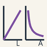
With V=EL and I=JA, R=ρL/A: a straight line in L, a hyperbola in A.
A perfect crystal would conduct perfectly: lattice vibrations and defects cause resistance, so a metal's ρ rises with T.
R=ρL/A fails below the mean free path (about 40 nm in copper) and at high frequency, where the skin effect crowds the current outward.
Current density and charge conservation
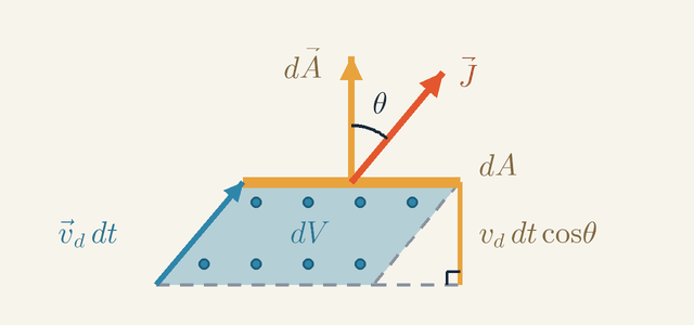
A current I says how much charge crosses a whole cross-section each second, but not how the flow is spread over it. The current density J does. Its size is the current per unit area at right angles to the flow, in A/m², and it points the way positive charge flows. To connect it with the carriers themselves, we count how many of them cross one small patch of a surface in a short time.
Figure 1. A small patch of area dA, seen edge-on, with its vector dA. Positive carriers drift with vd at the angle θ to dA. In the time dt exactly those in the slab of volume dV cross the patch; its height is vddtcosθ, not vddt.Legend
dA
Area of the small patch, drawn edge-on.
m2
dA
The patch as a vector: length dA, at right angles to the patch.
m2
J
Current density, nqvd: current per unit area, along the flow of positive charge.
A/m2
θ
Angle between J (and vd) and dA.
rad
vddt
How far the carriers drift in the time dt: the slanted edge of the slab.
m
vddtcosθ
The same drift measured at right angles to the patch: the height of the slab.
m
dV
Volume of the slab below the patch: the carriers in it cross the patch within dt.
m3
Figure 1 shows such a patch edge-on: the line labelled dA, its area. To say which way the patch faces, we give it a vector dA, of length dA and at right angles to the patch. The carriers, n of them per unit volume and each with charge q, are the dots. On average they move with the drift velocity vd, which makes the angle θ with dA. Their fast random motions carry as many carriers across the patch one way as the other, so only the drift counts.
In a short time dt each carrier moves by vddt. The carriers that cross the patch in that time are therefore exactly those that start in the slanted slab below it: any carrier further back cannot reach the patch in time. Look at the two sides of the slab. Its slanted edge, along the drift, is vddt long, but its height at right angles to the patch is only vddtcosθ. A slanted slab has the same volume as an upright one with the same base and height, so dV=dAvddtcosθ The slab holds the charge nqdV, and all of it crosses the patch within dt. Dividing by dt gives the current through the patch: dI=nqvdcosθdA=J⋅dA,J=nqvd The factor cosθ is exactly what a dot product supplies. Adding up the patches of a whole surface gives the current through it: I=∫J⋅dA For a uniform flow straight through a cross-section A, θ=0 everywhere, the integral is simply JA, and I=nAvdq
Figure 1 is drawn for positive carriers, q>0, where J and vd point the same way. For electrons q=−e, so J points against vd: the conventional current flows one way while the electrons drift the other.
Now take a closed surface, for example a box around a junction, with every dA pointing outwards. Charge is conserved: it cannot appear or vanish. So the current flowing out of the surface must come from the charge Q inside it, which decreases at the same rate: ∮J⋅dA=−dtdQ In a steady state nothing piles up anywhere, so dQ/dt=0: as much current enters any closed surface as leaves it. Applied to a piece of wire between two cross-sections, this says the same current crosses every section, whatever the wire's shape, so current is never used up. Applied to a junction of wires, it is the junction rule for circuits.
Drift from random collisions
A steady field pushes each carrier with a steady force, yet the current is steady too: the carriers do not speed up for ever. Collisions are what stop them. A carrier of mass m feels the force F=qE from the field, plus brief random kicks from collisions. The mean free time, τ, is the average time between collisions. Drude's model of 1900 describes this motion with three assumptions.
Between collisions the carrier moves freely, accelerating at F/m.
Each collision sends it off in a random direction, with no memory of how it was moving before.
Collisions strike at random, with the same chance dt/τ in every short time dt, whatever happened earlier.
Now look at all the carriers at one instant. Each carrier's velocity has two parts. The first is the velocity it left its last collision with: random, so it averages to zero over many carriers. The second is what the force has added since then, F/m times the time since that collision. So the average velocity, the drift, is F/m times the average time since the last collision.
What is that average? Because collisions have no memory, the chance of one in any short interval is dt/τ whether we run time forwards or backwards. Looking back from any instant, the time since the last collision therefore has the same statistics as the wait until the next one, and it also averages τ. Hence vd=mFτ and for an electron in a field E, with F=eE, vd=meEτ
Why the long flights dominate
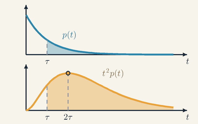
This result invites a doubt. During one flight the added velocity grows from zero to Ft/m, so surely the drift should be half of Fτ/m? It would be, if every flight lasted exactly τ. They do not: because collisions strike at random, the duration t of a flight is spread out, with the probability density p(t)=e−t/τ/τ. A fraction p(t)dt of all flights last between t and t+dt.
Figure 2. Free flights between collisions in Drude's model. Top: the density p(t) of the flight duration t, with mean τ. Bottom: each flight weighted by the distance it gains, which grows as t2; t2p(t) peaks at 2τ. Shaded: flights longer than τ, 37 % of flights but 92 % of the distance.Legend
t
Duration of one free flight, between two collisions.
s
τ
Mean free time: the average duration of a flight.
s
p(t)
Density of the flight duration, e−t/τ/τ: a fraction p(t)dt of flights last between t and t+dt.
s−1
t2p(t)
Forward distance contributed by flights of duration t: t2 times how common they are, up to the factor F/2m.
s
The top graph of Figure 2 is this density. It is highest for the shortest flights and falls steadily, and its mean is τ. Yet most flights are shorter than the mean: those longer than τ, the shaded part, are only 1/e, about 37 %, of all flights.
Now weigh each flight by how far it carries the carrier forward. Starting with no added velocity, a flight of duration t advances it by 21(F/m)t2=(F/2m)t2, so a flight twice as long gains four times the distance. The lower graph shows t2p(t): how common flights of duration t are, times how much each one contributes. It peaks at 2τ, well beyond the mean, and most of its area lies in the shaded part: the flights longer than τ supply about 92 % of the forward distance. The few long flights do almost all of the work, because they gather speed for longer. Taking half of Fτ/m treats every flight as equally long and misses exactly this.
The drift is the mean forward distance per flight divided by the mean duration of a flight: vd=2mFtt2=2mFτ2τ2=mFτ Here t=τ is the mean of p(t), and t2=2τ2 is the area under the lower curve: for random collisions the mean of t2 is twice the square of the mean. The random velocities with which flights begin add nothing on average, so this is the whole drift, and it agrees with the result above.
The magnified wire in the animation obeys the same rule. Each free flight is a short parabola bending to the right; with a mean free time of 12/45 ≈ 0.27 s and an acceleration of 22.5 units/s², the drift is aτ=22.5⋅12/45=6 units per second.
Ohm's law, resistivity and resistance
With the drift known, the current density follows. For carriers of charge q, the force is F=qE, so vd=qEτ/m and J=nqvd=mnq2τE The current density is proportional to the field. This is Ohm's law in its local form, true at each point of the metal. The constant of proportionality is the conductivity σ, and its inverse is the resistivity ρ; for electrons, with q2=e2, J=σE ρ=σ1=ne2τm Because the charge enters squared, positive and negative carriers give the same conductivity: measuring σ cannot reveal the sign of the carriers.
Check this against copper. With n=8.5×1028m−3 and τ=2.5×10⁻¹⁴s, the formula gives copper's measured 1.7×10⁻⁸Ωm. The agreement is less impressive than it looks: τ cannot be measured directly and was inferred from that very resistivity. The model explains the form of the law, a current proportional to the field, but not the size of ρ.
Now go from one point to a whole wire. In a uniform wire of length L and cross-section A the field is the same everywhere, so the voltage across the wire is V=EL and the current is I=JA. Putting E=V/L and J=I/A into J=σE gives I/A=V/(ρL), that is V=(ρL/A)I. So R=AρL is derived, not guessed.
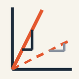
The two graphs in the animation's expert layer show its two faces, using the reference wire of the intermediate level: nichrome, 1.0 m long and 0.55 mm² in section, so 2 Ω, carrying 1.0 A at 2.0 V. Against length, R is a straight line through the origin with slope ρ/A: the reference wire sits at L0 and 2 Ω, the wire twice as long at 2L0 and 4 Ω. Against area, R is a hyperbola, because RA=ρL stays constant: the reference wire sits at A0 and 2 Ω, the thick wire at 2A0 and 1 Ω.
The hyperbola shows diminishing returns. Doubling the area saves 1 Ω, but going on to 3A0 saves only 0.33 Ω more, while shrinking the cross-section towards zero sends R to infinity.
Where the energy goes
Between collisions the field does work on each carrier and speeds it up. At each collision the carrier hands that energy to the lattice of ions, which vibrates harder: the wire warms up. On average the field delivers the power F⋅vd=qE⋅vd to each carrier, and there are n carriers per unit volume, so the heat produced per unit volume per second is p=J⋅E=σE2=ρJ2 Over a uniform wire, multiplying by its volume AL gives (JA)(EL)=IV, the familiar electrical power.
For the reference wire, E=2.0V/m and J=1.0/(0.55×10−6)≈1.8×106A/m2, so p=JE≈3.6×10⁶W/m3. The wire holds 0.55 cm³ of metal, so it produces 2.0 W in all, the same as IV=1.0⋅2.0W.
How the energy gets in
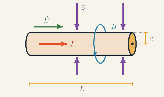
How does this energy reach each part of the wire? Not by travelling along the inside of it: the carriers pass their energy to the lattice right where they are. It flows in through the wire's surface, carried by the electric and magnetic fields in the space around it.
Figure 3. A wire carrying I, seen from the side. Just outside it E points along the wire and B circles it, so the energy flux S points into the wire from every side. Over the surface 2πaL the inflow adds up to VI, the heat produced inside. Not to scale.Legend
I
Current in the wire.
A
a
Radius of the wire.
m
L
Length of the wire.
m
E
Electric field just outside the surface: its part along the wire, the same as inside.
V/m
B
Magnetic field of the current, circling the wire by the right-hand rule: towards you at the top, away from you at the bottom.
T
S
Energy flux E×B/μ0: energy per second through unit area, here into the wire.
W/m2
Figure 3 shows a wire of radius a and length L carrying the current I to the right. Two fields surround it. The first is the electric field E just outside the surface, pointing along the wire. It is there because the part of a field that is parallel to a surface is the same on both sides of it, so the field that drives the current inside continues just outside. Surface charges may also add a part at right angles to the surface, but that part moves energy along the wire, not into it. The second is the magnetic field B of the current, which circles the wire by the right-hand rule and has the size B=μ0I/(2πa) at the surface.
Where both fields are present, electromagnetic energy flows. Its flux, the energy per second through unit area, is S=E×B/μ0, at right angles to both fields. Read the directions off the figure. At the top of the wire E points along it and B points towards you, so S points down, into the wire. At the bottom B points away from you, and S points up, again into the wire. All round, the energy flows straight in through the surface.
It remains to find how much energy flows in. Since E and B are at right angles, and the surface has the area 2πaL, S=μ0EB=2πaEI,S⋅2πaL=ELI=VI because EL=V: the inflow is exactly the heat produced inside. For the reference wire a≈0.42mm and S≈760W/m2, which over its surface of about 2.6×10⁻³m2 is exactly the 2.0 W of heat. The battery's energy travels through the space around the circuit; the wires guide it and take it in.
What really scatters the electrons
Drude pictured electrons bouncing off every ion. That picture is wrong, and correcting it explains how resistance depends on temperature and purity. First, the electrons of copper are not slow. The exclusion principle allows only one electron in each quantum state, so they fill states up to the Fermi speed, about 1.6×10⁶m/s, even at absolute zero. Their mean free path, the distance between collisions, is then ℓ=vFτ≈39nm, some 150 ion spacings: an electron passes many ions without being scattered.
The reason is that an electron is a wave. In a perfectly periodic lattice, the waves scattered by the individual ions combine to carry the electron straight on. A perfect crystal would have no resistance at all.
Only departures from perfect periodicity scatter electrons, and their scattering rates add (Matthiessen's rule). Lattice vibrations grow with temperature. Impurities and defects do not, and leave a residual resistivity even at the lowest temperatures.
Near room temperature the vibrational part is roughly proportional to the absolute temperature T, and a resistivity proportional to T changes by the fraction 1/T per kelvin. That is why copper's temperature coefficient α=3.9×10⁻³K−1 is close to 1/(293K)=3.4×10−3K−1, and ρ(T)≈ρ0(1+αΔT) is simply the linear term of ρ(T) around 20 °C. On cooling, the vibrations die away and ρ levels off at the residual value: very pure copper at 4 K conducts a hundred to a thousand times better than at room temperature.
Two other kinds of material behave quite differently. In a semiconductor, heat lifts electrons into conducting states, so n climbs steeply and ρ falls as it warms. A superconductor, below its critical temperature (about 4.2 K for mercury), has exactly zero resistance. Its electrons form one collective quantum state that carries a current without scattering: a new state of matter, not the limit of ever fewer collisions.
Worked problem: a wire that thickens
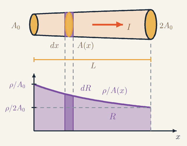
R=ρL/A holds for a uniform wire. What if the cross-section changes along the length? Take the reference wire (nichrome, 1.0 m, so ρ/A0=2.0Ω/m) and let it widen steadily from A0 at one end to 2A0 at the other, A(x)=A0(1+x/L), with 2.0 V across it. Its resistance must lie between the thick wire's 1 Ω and the reference wire's 2 Ω, but where?
Figure 4. A wire that widens from A0 to 2A0, cut into slices in series. Below it, the resistance per unit length ρ/A(x): the dark strip is one slice's dR=ρdx/A(x), and the whole area under the curve is the wire's resistance R. Not to scale.Legend
I
Current: the same through every slice.
A
A0
Cross-section at the thin end; the thick end has 2A0.
m2
A(x)
Cross-section at the distance x from the thin end, A0(1+x/L).
m2
L
Length of the wire.
m
x
Distance from the thin end.
m
dx
Thickness of one slice.
m
ρ/A(x)
Resistance per unit length of the wire at x.
Ωm−1
ρ/A0
Resistance per unit length at the thin end.
Ωm−1
ρ/2A0
Resistance per unit length at the thick end: half that at the thin end.
Ωm−1
dR
Resistance of the slice at x, ρdx/A(x): the area of the dark strip.
Ω
R
Resistance of the whole wire: the area under the curve.
Ω
Figure 4 cuts the wire into thin slices (wire and slice are drawn far thicker than they are). The slice at the distance x from the thin end has the thickness dx and the cross-section A(x). So thin a slice is a short uniform wire, with the resistance dR=ρdx/A(x). The same current I passes through one slice after another, so the slices are in series and their resistances add.
The graph below the wire turns this sum into an area. Its curve is the resistance per unit length, ρ/A(x), which falls from ρ/A0 at the thin end to ρ/2A0 at the thick end. The dark strip under the curve has the height ρ/A(x) and the width dx, so its area is the slice's dR. Adding up all the strips gives the whole area under the curve, which is the resistance R of the wire. With u=1+x/L, so that dx=Ldu, R=∫0LA0(1+x/L)ρdx=A0ρL∫12udu=A0ρLln2 R=2.0⋅0.693≈1.39Ω
So the current is I=2.0/1.386≈1.44A. Two tempting shortcuts both fail. Averaging the two resistances gives 1.5 Ω, too high, because the curve sags below the straight line joining its ends. Using the average area, 1.5A0, gives 1.33 Ω, too low, because the slices add as 1/A, and the mean of 1/A is not one over the mean of A. The slice picture itself is safe here because the wire widens gently: its diameter grows only from 0.84 mm to 1.18 mm over a whole metre, so the current in each slice flows almost straight along the wire.
The current is the same through every slice, so the field must follow the area: E(x)=ρI/A(x) is 2.9 V/m at the thin end and 1.4 V/m at the thick end, and 1.17 V of the 2.0 V, 58 %, falls across the thinner half. The drift is twice as fast at the thin end as at the thick end, and the heat there is twice as large per unit length and four times as large per unit volume. What shapes the field this way is a thin layer of surface charge, set up within nanoseconds of switching on. The same concentration of heat at a narrow section is why fuse elements have deliberate narrow necks: that is where they melt.
Limits of validity
R=ρL/A treats the metal as a continuum, with a definite ρ at each point, so every dimension of the conductor must be much larger than the mean free path, about 40 nm in copper. In thin films and in chip interconnects a few tens of nanometres wide, electrons also scatter at the surfaces and at grain boundaries, and the resistivity rises two or three times above its bulk value. Conductors shorter than the mean free path are crossed without any collision, and resistance takes on a quantum character: a constriction a few atoms wide conducts in steps of 2e2/h≈7.75×10−5S, 12.9 kΩ per channel, whatever the metal.
The results also assume a steady current. In an alternating current, the changing magnetic field inside the wire induces an electric field that opposes the current near the axis and adds to it near the surface. The current crowds into a surface layer whose thickness, the skin depth, is δ=ωμ02ρ where ω is the angular frequency. For copper that is 9.3 mm at 50 Hz, 66 µm at 1 MHz and 2.1 µm at 1 GHz, so at high frequency only a thin skin of the wire carries current. Near 1/(2πτ)≈6THz the field reverses within about one free time, and the inertia of the electrons, not their collisions, starts to set their response; that response to light is what makes metals shiny.
Ohm's law also needs the energy a carrier gains between collisions to be tiny. In copper carrying 1 A per mm², the field is only 0.017 V/m, and an electron gains about 7×10⁻¹⁰eV over one free path, against the thermal energy scale kT≈0.026eV at room temperature. In strong fields this fails: the electrons of a semiconductor heat up, and in silicon their drift speed saturates near 105m/s instead of growing with the field.
Where this leads
DC Circuits and Ohm's Law builds on this: resistors in series add like lengths of wire, and in parallel they act like extra lanes, so their conductances add. Electric Power and Energy at Home follows the heat VI=I2R into cables, fuses and kettles. A current makes a magnetic field (Magnetic Fields of Magnets and Currents), and a magnetic field deflects the drifting carriers (Magnetic Force on Moving Charges), producing a Hall voltage that reveals n and the sign of q. Semiconductors, Diodes and LEDs controls n to build devices, and Electromagnetic Waves meets the same skin depth when a radio wave enters seawater. Since the free electrons carry heat too, good electrical conductors are good conductors of heat (Conduction, Convection and Radiation).
Key formulas
Current as charge per unit time
I=tQ
Current counts how much charge crosses a cross-section of the conductor each second. For a steady current the charge grows in proportion to the time, so a graph of Q against t is a straight line whose slope is I; for a changing current the same idea at one instant reads I=dQ/dt. By convention the current points the way positive charge would flow.
Symbols
I
current
A
Q
charge that crosses the cross-section in the time t
C
t
time taken
s
When it holds: Gives the average current over the time t; it equals the current at every instant only if the current is steady.
Example: The reference wire in the animation carries 1.0 A, so in the 12 s loop Q=1.0⋅12=12C pass, about 7.5×10¹⁹ electrons.
Definition of resistance
R=IV
Resistance is the voltage needed to drive each ampere through a component: a large R means a small current for a given push. The formula is a definition and applies to anything. Ohm's law is a separate, experimental fact: for a metal at a fixed temperature this ratio does not depend on V.
Symbols
R
resistance
Ω
V
voltage across the component
V
I
current through it
A
When it holds: Defines R for any component at any working point, but R is a constant only for ohmic conductors at a fixed temperature: a lamp filament's ratio grows more than tenfold as it heats, and a diode's depends on the direction of the current.
Example: The middle wire in the animation: 2.0 V drives 0.50 A, so R=2.0/0.50=4.0Ω.
Resistance of a uniform wire
R=AρL
A wire behaves like many short pieces in series, whose resistances add, and like many lanes side by side, which share the current. So its resistance grows in proportion to the length and falls in inverse proportion to the cross-sectional area, while the material enters through its resistivity ρ. The formula follows from the local law J=σE with V=EL and I=JA.
Symbols
R
resistance of the wire
Ω
ρ
resistivity of the material
Ωm
L
length of the wire
m
A
cross-sectional area
m2
When it holds: For a uniform wire with a steady current spread evenly over its section. It fails for films and wires thinner than the mean free path (about 40 nm in copper) and at high frequency, where the skin effect pushes the current outward; ρ also changes with temperature.
Example: Nichrome, ρ=1.1×10⁻⁶Ωm, 1.0 m long with a 0.55 mm² section: R=1.1×10−6⋅1.0/(0.55×10−6)=2.0Ω.
Current from the drift of carriers
I=nAvdq
In a time Δt every carrier within a distance vdΔt upstream of a cross-section gets through it. That slab has a volume AvdΔt and holds nAvdΔt carriers, so their charge divided by Δt is the current. A large current needs many carriers rather than fast ones: in a metal n is huge and vd tiny.
Symbols
I
current
A
n
number of free carriers per unit volume
m−3
A
cross-sectional area
m2
vd
drift speed of the carriers
m/s
q
charge of one carrier
C
When it holds: Holds for any conductor with one kind of carrier, vd being their average velocity along it; when there are several kinds (electrons and holes, positive and negative ions), their contributions add.
Example: Copper, n=8.5×1028m−3, carrying 1 A in 1 mm²: vd=1/(8.5×1028⋅10−6⋅1.602×10−19)≈7.3×10−5m/s.
Ohm's law in local form
J=σE
At each point inside a conductor the current density is proportional to the electric field there. The conductivity σ belongs to the material alone, so this form says nothing about the shape of the wire; applied to a uniform wire it gives V=RI. In an ohmic material J points along E.
Symbols
J
current density
A/m2
σ
conductivity of the material
S/m
E
electric field in the conductor
V/m
When it holds: For ohmic materials at moderate fields and at frequencies well below 1/(2πτ), about 6 THz for copper. It fails in semiconductors at high fields, where the drift saturates, and in superconductors.
Example: In copper, σ=5.9×10⁷S/m, a current of 1 A per mm², that is J=106A/m2, needs only E=J/σ≈0.017V/m.
Drift speed from the collision model
vd=meEτ
Between collisions the field accelerates an electron at eE/m, and each collision randomises its velocity. At any instant the time since an electron's last collision averages τ, so its extra velocity averages eEτ/m, not half of it: long free flights carry more weight. The electrons drift against E because their charge is negative; the formula gives the speed.
Symbols
vd
drift speed
m/s
e
elementary charge
C
E
electric field
V/m
τ
mean free time between collisions
s
m
electron mass
kg
When it holds: Assumes collisions that strike at random and erase the velocity gained. In the quantum theory of metals m becomes an effective mass and τ the scattering time of electrons at the Fermi speed.
Example: Copper, τ=2.5×10⁻¹⁴s, in a field of 0.017 V/m: vd=1.602×10−19⋅0.017⋅2.5×10−14/(9.11×10−31)≈7.5×10−5m/s. This matches the 7.3×10⁻⁵m/s found from I=nAvdq to within the rounding of τ.
Drude resistivity
ρ=σ1=ne2τm
Putting the drift speed into J=nevd gives J=(ne2τ/m)E, so the conductivity is ne2τ/m and the resistivity its reciprocal. Resistivity is low when the carriers are many, light and long-lived between collisions. The charge appears squared, so the formula cannot tell negative carriers from positive ones.
Symbols
ρ
resistivity
Ωm
σ
conductivity
S/m
m
electron mass
kg
n
number of free electrons per unit volume
m−3
e
elementary charge
C
τ
mean free time between collisions
s
When it holds: A classical model that gets the form right, with τ taken from the measured resistivity. Quantum mechanics explains why τ is so long: only departures from a perfect lattice scatter electrons.
In a metal, hotter ions vibrate more and scatter the electrons more often, so τ shrinks and ρ grows, roughly in proportion to the absolute temperature near room temperature. Over a moderate range this is well described by a straight line through the value ρ0 at a reference temperature, usually 20 °C, with slope αρ0. For semiconductors α is negative, because heat frees more carriers.
Symbols
ρ
resistivity at the temperature T
Ωm
T
temperature
K
ρ0
resistivity at the reference temperature
Ωm
α
temperature coefficient of resistivity
K−1
ΔT
rise of temperature above the reference temperature
K
When it holds: A first-order approximation, good over a few hundred kelvins for metals. It fails near absolute zero, where the resistivity levels off at a residual value, or drops to zero in a superconductor.
Example: A copper cable that warms from 20 °C to 60 °C in the sun: its resistance grows by the factor 1+3.9×10−3⋅40≈1.16, that is by 16 %.
Glossary
Electric current
A net flow of electric charge, carried by free electrons in metals and by ions in salt solutions, batteries and gases. Its size is the charge crossing a cross-section per second, I=Q/t; in a steady state the same current crosses every section of a wire, so it is never used up.
Conventional current
The direction given to a current: the way positive charge would move, from + to − through the outside circuit and along the field inside a conductor. Electrons, being negative, drift the opposite way.
Drift velocity
The slow average velocity vd of the carriers along a conductor, superposed on their fast random motion. In copper carrying 1 A per mm² it is about 0.07 mm/s, while the random speeds are near 1.6×10⁶m/s.
Current density
The current per unit cross-sectional area, J=I/A in A/m², pointing along the flow of positive charge. It describes the flow at each point rather than through the whole wire, and equals nqvd for carriers of density n and charge q.
Potential difference (voltage)
The potential difference V between two points, in volts: the energy each coulomb of charge gives up in moving from one to the other, 1V=1J/C. It is the push that drives a current through a resistance.
Resistance
How strongly a component opposes a current: the voltage needed per ampere, R=V/I, in ohms. It depends on the shape of the component as well as its material, unlike resistivity, which belongs to the material alone.
Resistivity
A property of a material, not of a particular wire: ρ=RA/L, the resistance of a piece 1 m long with a cross-section of 1 m². It ranges from 1.7×10⁻⁸Ωm for copper to more than 1010Ωm for glass.
Ohm's law
The experimental fact that, for many materials at a fixed temperature, the current is proportional to the voltage, so R is a constant; in local form, J=σE. It describes metals well, but not lamp filaments, diodes or gas discharges.
Conductors, semiconductors and insulators
The three classes of materials by resistivity: metals at about 10−8 to 10−6Ωm, insulators above about 1010Ωm, and semiconductors in between. A semiconductor's resistivity falls as it warms and depends strongly on its purity.
Mean free time and mean free path
The average time τ between two collisions of a carrier, and the average distance it covers in that time. In copper at room temperature they are about 2.5×10⁻¹⁴s and 40 nm.
Joule heating
The warming of a conductor that carries a current: the energy the field gives the carriers passes to the lattice in collisions. Its rate is VI=I2R, or ρJ2 per unit volume.
Skin effect
The crowding of an alternating current into a layer near the surface of a conductor, because the changing magnetic field inside induces an electric field that opposes the current near the axis. In copper the layer is 9.3 mm thick at 50 Hz but only 2.1 µm at 1 GHz.
Quantities
I
Current
A
The charge crossing a cross-section per second; 1A=1C/s, about 6.2×10¹⁸ electrons per second.
Q
Charge
C
The amount of charge that has passed in a time t, Q=It; the counters in the animation show it.
E
Electric field
V/m
The force per unit charge inside the conductor that drives the carriers; in a uniform wire E=V/L, which is 2.0 V/m in the reference wire of the animation.
R
Resistance
Ω
Voltage per unit current, V/I, where V is the voltage across the component, in volts; a resistance of 1Ω needs 1 V to drive 1 A.
ρ
Resistivity
Ωm
The material's opposition to a current, whatever the shape of the sample: ρ=RA/L for a wire of length L (in m) and cross-sectional area A (in m²).
σ
Conductivity
S/m
The reciprocal of the resistivity, σ=1/ρ: the current density J (in A/m²) per unit field, J=σE. About 5.9×10⁷S/m for copper.
n
Carrier density
m−3
The number of free charge carriers per cubic metre; 8.5×1028m−3 in copper, about one per atom. With the charge q of one carrier (in C) and their drift speed vd (in m/s) it gives I=nAvdq.
e
Elementary charge
C
The size of the charge of one electron, 1.602×10⁻¹⁹C; an electron carries q=−e. With the electron mass m=9.11×10⁻³¹kg it sets the acceleration eE/m between collisions.
τ
Mean free time
s
The average time between two collisions of a carrier; about 2.5×10⁻¹⁴s in copper at room temperature.
α
Temperature coefficient of resistivity
K−1
The fractional change of resistivity per kelvin of warming: 3.9×10⁻³K−1 for copper, negative for semiconductors. It enters ρ(T)≈ρ0(1+αΔT), where ρ0 is the resistivity at the reference temperature and ΔT the warming above it, in kelvins.
Quiz
Beginner When a copper wire carries a current, which particles actually move along it?
The copper ions
Protons pushed out of the battery
Free electrons
Nothing moves: only energy flows
Show answer
Answer: C. Free electrons
In a metal the outer electrons are free to move, while the positive ions stay in place in the lattice and protons stay locked in the nuclei. The battery's push makes the free electrons drift along the wire.
Beginner You flip a switch and the ceiling lamp lights at once. Why?
Electrons leave the switch and race to the lamp at nearly the speed of light
The wire is already full of electrons, and the push reaches all of them almost at once
The lamp stores charge and releases it when the switch closes
Electricity jumps through the air from the switch to the lamp
Show answer
Answer: B. The wire is already full of electrons, and the push reaches all of them almost at once
Electrons drift very slowly, but they are present everywhere in the circuit. Closing the switch sets up the push (the electric field) along the whole wire almost at light speed, so the electrons in the lamp start moving straight away.
Beginner Two wires of the same metal and thickness are connected in turn to the same battery. One is twice as long as the other. What happens in the longer wire?
Twice as much current flows
The same current flows
No current flows at all
Half as much current flows
Show answer
Answer: D. Half as much current flows
Along a wire twice as long, the electrons meet twice as many ions, so the resistance doubles. With the same battery, only half as much charge gets through each second, like the long wire in the animation.
Intermediate A phone charger delivers 2.0 A for 30 minutes. How much charge flows through the cable?
3600 C
60 C
900 C
15 C
Show answer
Answer: A. 3600 C
Q = I·t with t in seconds: 30 min = 1800 s, so Q = 2.0 × 1800 = 3600 C. Forgetting to convert the minutes gives 60 C; dividing instead of multiplying gives 900 C or 15 C.
Intermediate In a metal wire, the conventional current I flows to the left. Which way do the electrons drift?
To the left, with the current
They do not move; only the field moves
To the right, against the current
Across the wire, from one side to the other
Show answer
Answer: C. To the right, against the current
Conventional current is defined as the direction in which positive charge would move. Electrons are negative, so they drift opposite to I and to the field E, as the v_d arrow in the animation shows.
Intermediate A wire has a resistance of 6.0 Ω. What is the resistance of a wire of the same material that is twice as long and has twice the cross-sectional area?
24 Ω
6.0 Ω
12 Ω
3.0 Ω
Show answer
Answer: B. 6.0 Ω
R = ρ·L/A. Doubling L doubles R and doubling A halves it, so the two changes cancel and R stays 6.0 Ω. 24 Ω comes from multiplying both effects, 12 Ω and 3.0 Ω from applying only one of them.
Advanced A copper wire (n = 8.5 × 10²⁸ m⁻³) with a cross-section of 2.0 mm² carries 3.0 A. What is the drift speed of its electrons?
About 3 × 10⁸ m/s
1.6 × 10⁶ m/s
1.1 × 10⁻⁷ m/s
1.1 × 10⁻⁴ m/s
Show answer
Answer: D. 1.1 × 10⁻⁴ m/s
v_d = I/(n·A·e) = 3.0 ÷ (8.5 × 10²⁸ × 2.0 × 10⁻⁶ × 1.602 × 10⁻¹⁹) ≈ 1.1 × 10⁻⁴ m/s, about 0.1 mm/s. 1.6 × 10⁶ m/s is the random speed of the electrons, the signal moves at nearly c, and 1.1 × 10⁻⁷ m/s comes from taking 1 mm² = 10⁻³ m².
Advanced According to the Drude model, why does the resistivity of a metal increase when it gets hotter?
Stronger lattice vibrations shorten the mean free time τ
Heat frees more electrons, increasing n
The electrons become heavier, increasing m
Thermal expansion makes the wire longer, so L increases
Show answer
Answer: A. Stronger lattice vibrations shorten the mean free time τ
ρ = m/(n·e²·τ). In a metal n and m hardly change, but hotter ions vibrate more and scatter the electrons more often, so τ drops and ρ rises, by about 0.4 % per kelvin for copper. Freeing more carriers with heat is what happens in semiconductors, whose ρ falls instead. Thermal expansion changes L and A by less than 0.004 % per kelvin, and these set R, not the material property ρ.
 Physics Tutor