Two plates that store separated charge, Q=CV, and energy, W=21CV2; charged through a resistor, they fill quickly at first and then ever more slowly, at a pace set by τ=RC.
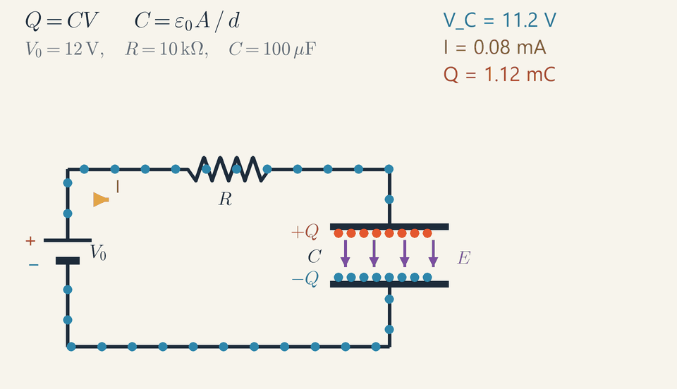
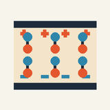
A capacitor charging from a 12 V battery through a resistor. Electrons drift through the wires, quickly at first and then more slowly, while charge piles up on the plates and the field between them grows.
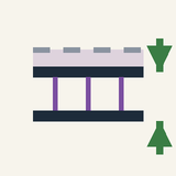
A capacitor is two metal plates separated by a thin insulating gap; it stores separated charge, and with it energy.
The battery moves electrons through the wires from one plate to the other, so the plates get equal and opposite charges.
No charge crosses the gap: the + and − plates attract each other through it, and an electric field fills it.
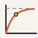
Charging is quick at first, then slows and stops when the capacitor's voltage matches the battery's.
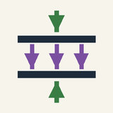
Bigger plates or a narrower gap let the same battery store more charge.
Camera flashes, heart defibrillators and the circuits in your phone all depend on capacitors. A capacitor is one of the simplest electrical parts: two metal plates facing each other across a thin gap of air or plastic. It stores separated electric charge, and with it energy, which it can give back in a split second.
Step 1: moving electrons. Metals contain electrons that are free to move. Connect the plates to a battery and it pulls electrons off one plate and pushes them, through the wires, onto the other. One plate is left positive, the other turns negative. No electron is created or destroyed: each one that lands on one plate was taken from the other, so the two charges are always equal and opposite.
Step 2: nothing crosses the gap. The gap is an insulator, so charge cannot jump across it. Instead the + plate and the − plate attract each other through it, and an electric field fills the space between them.
Step 3: filling up. The more charge the plates already hold, the harder they push back against the battery. Charging is therefore quick at first, then slows, and stops when the capacitor's voltage equals the battery's, just as a tank fed from a water tower stops filling when the two levels match.
Step 4: size matters. Larger plates or a narrower gap let the same battery store more charge.
In the animation the blue electrons race through the wires at first, then slow down and stop, while charge piles up on the plates and the gauge fills ever more slowly.
Check yourself: one plate of a charged capacitor carries +5 units of charge. What does the other carry? (Answer: −5 units; the total is still zero.)
Intermediate
Key ideas
Q=CV: the capacitance C, in farads (1F=1C/V), is the charge stored per volt.
Parallel plates: C=ε0εrA/d, so a larger area, a smaller gap or a dielectric raises C.
Through a resistor, I=(V0−VC)/R: largest (V0/R) at the start, falling as VC rises.
Stored energy W=21CV2=21QV, not QV, because V rises from 0 while the charge is moved.
Charge, voltage and capacitance
Before a camera flash fires, a capacitor collects its energy slowly; the flash then releases it in one brief burst. A capacitor is any pair of conductors separated by an insulator, most simply two metal plates across a thin gap. A battery moves charge through the wires from one plate to the other, leaving +Q on one and −Q on the other, so the capacitor as a whole stays neutral and its charge means Q. Its voltage V is the potential difference between the plates, the work per coulomb to carry charge from the negative plate to the positive one.
Double the charge and the field between the plates doubles everywhere, and so does the work per coulomb. Charge and voltage are therefore proportional: Q=CV
The constant C is the capacitance, the charge stored per volt, measured in farads: 1F=1C/V. A farad is enormous, so most capacitors are rated in picofarads (10−12F), nanofarads or microfarads (µF, 10−6F).
What sets the capacitance
For two flat parallel plates of area A a distance d apart, the field between them is uniform, E=V/d, and nearly zero outside. The capacitance depends only on this geometry and the insulator: C=dε0εrA
Here ε0≈8.85×10⁻¹²F/m is the permittivity of free space, and εr is the relative permittivity, or dielectric constant, of the insulator: 1.0006 for air, about 2.2 for polypropylene, 80 for water.
The charge per square metre fixes the field, E=Q/(ε0εrA), so larger plates spread the same charge thinner, and the field and the voltage V=Ed are smaller. A narrower gap keeps the field of the same charge but shortens the path across it. In a dielectric the molecules polarise, their negative ends turning towards the positive plate, and partly cancel the field. Each of these lowers the voltage per coulomb, so the same battery pushes on more charge.
Two plates of 1 cm² with a 0.5 mm air gap have C=8.85×10−12⋅10−4/(5×10−4)≈1.77pF; pressed to 0.3 mm, as in a capacitive key, they reach 2.95 pF. One farad with a 1 mm air gap would need 113 km² of plate.
Charging through a resistor
In the animation a battery of voltage V0 charges the capacitor through a resistor R. The battery's voltage is shared between them, V0=RI+VC, so only the voltage left over for the resistor drives the current: I=RV0−VC
At the start the capacitor is empty, VC=0, and the current is at its largest, V0/R, as if the capacitor were a plain wire. Each bit of charge that arrives raises VC, leaves less voltage for the resistor and slows the current: the fuller the capacitor, the gentler the push that fills it.
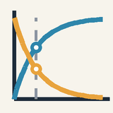
The pace is set by the time constant τ=RC; ohms times farads give seconds. After one time constant the capacitor has 63 % of its final voltage, and after 5τ more than 99 %. The exact laws, derived at the advanced level, are exponential:
τ=RC
VC=V0(1−e−t/RC)
I=(RV0)e−t/RC
Stored energy and the voltage–charge graph
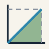
Charging takes work: each bit of charge must be carried across the voltage already built up, almost zero for the first bit and the full V for the last. On a graph of voltage against charge, V=Q/C is a straight line from the origin, and the work is the area under it, a triangle of base Q and height V: W=21CV2=21QV
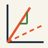
The ½ appears because the average voltage during charging is half the final one. Plotted as charge against voltage, the same line has slope C, so a larger capacitance gives a steeper line. Because W grows with the square of the voltage, doubling the voltage stores four times the energy, held in the field between the plates.
Worked example: the circuit in the animation
With the animation's V0=12V, R=10kΩ and C=100μF, the initial current, time constant, final charge and energy are I0=RV0=104Ω12V=1.2mA τ=RC=104Ω⋅10−4F=1s Q=CV0=10−4F⋅12V=1.2mC W=21CV02=21⋅10−4⋅122=7.2mJ
These are the readouts' end points: I starts at 1.20 mA, and once charging is over VC reads 12.0 V, Q 1.20 mC and I 0.00 mA. At t=τ=1s they show VC=7.6V (63 %), Q=0.76mC and I=0.44mA, as the loop rule confirms: (12−7.6)V/10kΩ=0.44mA.
The blue dots are electrons. They leave the top plate for the battery's positive terminal, and as many are pushed from the negative terminal onto the bottom plate, so the top plate becomes +Q (red-orange dots) and the bottom one −Q (blue dots). The gold arrow I, the conventional current, points against the electrons' drift and shrinks as the current dies. The purple arrows E between the plates grow in proportion to Q, and no dot ever crosses the gap.
Worked example: a camera flash
A camera flash stores its energy in a capacitor of, say, 150 µF charged to 300 V. It holds Q=CV=150×10−6⋅300=0.045C W=21CV2=21⋅150×10−6⋅3002=6.75J
Suppose the charger acts like a 300 V source behind 8 kΩ. Then τ=8000⋅150×10−6=1.2s and the current starts at 300/8000=37.5mA. After 2τ=2.4s the voltage is 300(1−e−2)≈259V, 86 %, but the energy, which goes with V2, is only 0.8652≈0.75 of the maximum, about 5.0 J.
The tube then empties the fully charged capacitor in about a millisecond, so the average power of the flash is 6.75J/10−3s≈7kW. A discharge time constant of 1 ms needs a resistance of only 10−3/(150×10−6)≈7Ω. The same capacitor fills slowly and empties fast: the resistance in its path sets the pace.
Common mistakes
Current does not flow through the gap: charge flows onto one plate as an equal charge flows off the other, so both wires carry the same current, 1.2 mA at the start in the animation, and none once the capacitor is full. A capacitor blocks a steady current.
A charged capacitor carries no net charge: the animation's plates end with +1.2mC and −1.2mC.
The stored energy is 21QV, not QV: 7.2 mJ in the animation, not 14.4 mJ, because the voltage rose from zero while the charge was moved.
One time constant does not fill the capacitor: it gives 63 % of the final voltage and only 40 % of the final energy. Allow about 5τ.
Kilo-ohms times microfarads give milliseconds: 2.2 kΩ with 47 µF gives τ≈0.10s, not 103 s.
Where you meet it
Camera flashes and defibrillators collect energy slowly and release it in milliseconds. Smoothing capacitors in power supplies fill up at the peaks of the alternating voltage and supply the current in between. Touchscreens sense the change of capacitance when a finger comes near, and each bit of a computer's main memory is a tiny capacitor, charged or empty.
The resistor and the loop rule are developed in Electric Current and Resistance and in DC Circuits and Ohm's Law. Joined to a coil (Electromagnetic Induction), a capacitor makes a circuit whose charge oscillates as in Simple Harmonic Motion, and resistance makes it a case of Damping and Resonance. The changing field in the gap of a charging capacitor acts as the displacement current, which completes the field equations and predicts Electromagnetic Waves.
Advanced
Key ideas
Rdq/dt+q/C=V0 gives VC=V0(1−e−t/τ) and I=(V0/R)e−t/τ, with τ=RC.
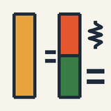
Charging from empty, the battery supplies CV02: half is stored, half becomes heat in R, whatever R is.
Virtual work: at fixed Q, Fdz=d(Q2/2C), so the plates attract with F=Q2/(2ε0A).
The energy sits in the field, u=21ε0E2, and while charging it flows in through the edges of the gap.
A dielectric's polarisation weakens the field for a given charge: C grows by εr until breakdown.
Why charge and voltage are proportional
Every result below rests on one fact: for any pair of conductors, the charge is proportional to the voltage. It is worth seeing why before using it.
Put +Q on one conductor and −Q on the other, with no other charges nearby. The field they make obeys linear equations: the field of several charges is the sum of their separate fields. Multiply every charge by the same factor and the field is multiplied by that factor at every point. The scaled arrangement still has zero field inside the metal and each conductor still at one potential, so it is the true arrangement for the larger charge. The voltage is the line integral of the field from the positive conductor to the negative one, V=∫E⋅dl, so it grows by the same factor as well.
Charge and voltage therefore rise together in a fixed ratio, Q=CV. The capacitance C is set by the shape and spacing of the conductors and by the insulator between them, never by Q or V. The recipe for finding it follows directly: assume a charge Q, find the field, integrate it to get V, and divide.
Parallel plates from Gauss's law
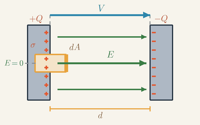
The simplest case is two flat plates of area A a small distance d apart. Gauss's law gives the field between them in one step, and Figure 1 shows how.
Figure 1. Two charged plates side on, with a Gauss box straddling the inner surface of the positive plate. Only its right face, of area dA, lies in the field E; the left face is in the metal, where E=0. Across the gap d, V=Ed. Not to scale.Legend
Q
Charge on each plate: +Q on the left plate, −Q on the right one.
C
σ
Charge per square metre on the inner surface of the positive plate, σ=Q/A for plates of area A.
C/m2
dA
Area of the right face of the Gauss box, the only face the field crosses.
m2
E
Electric field in the gap: uniform, from the positive plate to the negative one; zero inside the metal.
N/C
d
Width of the gap between the plates.
m
V
Voltage between the plates: the line integral of the field from the positive plate to the negative one, V=Ed.
V
Figure 1 shows the plates side on, with +Q on the left plate, −Q on the right one and the gap d between them. The positive charge sits on the inner surface of its plate, the side facing the negative plate, with a charge σ on each square metre; for plates of area A, σ=Q/A. The small box drawn across that surface is a Gauss box: an imaginary closed surface to which Gauss's law is applied.
Look at the two large faces of the box. The left face lies inside the metal, marked E=0. In a conductor at rest the field must vanish, or its free charges would still be moving. The right face, a patch of area dA, lies in the gap, and the field E crosses it at right angles. The other faces either run along the field or lie in the metal, so nothing flows through them. The flux out of the box is therefore EdA, and the charge inside it is σdA.
Gauss's law sets the flux out of a closed surface equal to the charge inside divided by ε0: EdA=ε0σdA The patch area dA cancels, so the size of the box does not matter, and the field in the gap is E=ε0σ=ε0AQ
Because σ is the same all over a large plate, this field has the same value everywhere in the gap, as the evenly spaced field lines of the figure show. Outside the pair, the fields of the two plates cancel.
Now the voltage. The arrow V in the figure runs across the gap from the positive plate to the negative one. Along it the field has the same value E at every step, so the line integral is simply E times the length d: V=Ed=ε0AQd,C=VQ=dε0A As promised, Q has dropped out. A larger area holds more charge per volt; a wider gap holds less. An insulator of relative permittivity εr filling the gap makes C larger by the factor εr, as the section on dielectrics explains.
The same recipe works for other shapes. Outside an isolated sphere of radius a the field is that of a point charge, and integrating it from the surface out to infinity gives V=Q/(4πε0a). In a coaxial cable with inner radius a and outer radius b, the field between the conductors falls as 1/r, so integrating it from a to b gives a logarithm. For the sphere, and for a cable of length ℓ with insulation of relative permittivity εr: C=4πε0a,ℓC=ln(b/a)2πε0εr
The numbers are telling. The whole Earth, as a sphere, has only about 0.71 mF, less than an ordinary 1000 µF electrolytic capacitor. A cable with polyethylene insulation (εr=2.3) and b/a=3.5 has about 100 pF per metre.
The charging equation and its solution
A capacitor is never charged instantly: some resistance in the circuit always limits the current. This section works out how the charge builds up over time, the law behind every timing circuit built from a resistor and a capacitor.
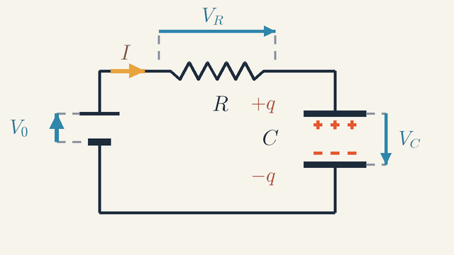
Figure 2. The charging loop. Going round it in the direction of I, the battery raises the potential by V0, and the resistor and the capacitor lower it by VR and VC, so V0=VR+VC. The current piles +q and −q on the plates.Legend
V0
Battery voltage: the rise in potential across the battery.
V
R
Resistance of the resistor.
Ω
C
Capacitance of the capacitor.
F
I
Current, the same all round the loop: the rate at which charge reaches the upper plate, I=dq/dt.
A
q
Charge on the capacitor at the instant drawn: +q on the upper plate, −q on the lower one.
C
VR
Drop in potential across the resistor, VR=RI.
V
VC
Drop in potential across the capacitor, VC=q/C.
V
Figure 2 shows the loop: a battery of voltage V0, a resistor R and a capacitor C in series. There is only one path, so the same current I flows through every part. At the instant drawn the capacitor carries +q on its upper plate and −q on its lower one; q grows from zero as the current brings charge.
Follow the potential once round the loop in the direction of I. The battery raises it by V0. The resistor lowers it by VR=RI (Ohm's law), and the capacitor lowers it by VC=q/C. Back at the starting point the potential must have its original value, so the rise equals the two drops together: V0=VR+VC
The current is the rate at which charge arrives on the upper plate, I=dq/dt. Writing VR=Rdq/dt and VC=q/C turns the loop rule into an equation for the charge alone: Rdtdq+Cq=V0 It is first order, because only the first derivative appears, and linear, because q appears only to the first power.
To solve it, multiply by C and rearrange: RCdq/dt=CV0−q. The right-hand side is the charge still missing from the final value CV0. Dividing both sides by it puts everything with q on one side and everything with t on the other: CV0−qdq=RCdt Integrate from an empty capacitor, q=0 when the switch closes at t=0, up to the charge q at time t: −ln(1−CV0q)=RCt
Undoing the logarithm gives q=CV0(1−e−t/RC). Dividing by C gives the capacitor's voltage, and differentiating q gives the current: VC=V0(1−e−t/RC) I=RV0e−t/RC The product τ=RC has the units of time, since Ω⋅F=s. It is called the time constant, and it sets the pace of everything that follows.
A first-order equation needs one initial condition, here q(0)=0. Notice what can and cannot jump when the switch closes. The current jumps at once from zero to V0/R. The charge cannot jump, because changing it in no time at all would need an infinite current; so a capacitor's voltage is always continuous. Discharging through R from a voltage V1 is the same equation with V0=0, and gives VC=V1e−t/RC.
Every quantity in such a circuit, charge, voltages and current alike, follows one pattern. A quantity x starts at x0 and heads for its final value x∞: x(t)=x∞+(x0−x∞)e−t/τ The reason is that its rate of change is proportional to the distance still to go, dx/dt=(x∞−x)/τ. As a result, equal times shrink that distance by equal factors: by e−1≈0.37 in each time constant, and by one half in each τln2≈0.69τ.
Reading the exponential graphs
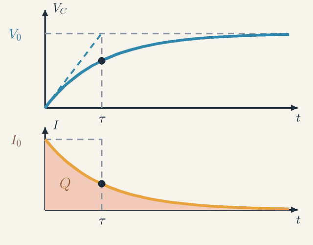
The solutions are easiest to grasp as graphs. They are drawn here for the animation's circuit: V0=12V, R=10kΩ and C=100μF, so that τ=RC=1s and the starting current is I0=V0/R=1.2mA.
Figure 3. Charging from empty: the voltage VC above, the current I below, on one time axis. At t=τ (dots) VC is at 63 % of V0 and I at 37 % of I0. The dashed tangent meets V0 at τ, and the shaded area Q equals the dashed rectangle.Legend
t
Time since the switch closed.
s
τ
Time constant, τ=RC: the time to cover 63 % of the change.
s
VC
Voltage of the capacitor, rising from zero towards V0.
V
V0
Battery voltage, the final value of VC.
V
I
Current in the loop, falling from I0 towards zero; I=CdVC/dt.
A
I0
Starting current, I0=V0/R.
A
Q
Total charge delivered: the shaded area under I(t), equal to I0τ=CV0.
C
Figure 3 draws the two solutions on a common time axis t. The upper graph is the capacitor's voltage VC, climbing from zero towards the battery voltage V0. The lower graph is the current I, falling from I0 towards zero. The dashed vertical line in each marks one time constant, t=τ. The animation's expert layer plots the same curves, each as a fraction of its maximum, VC in blue and I in gold.
Look first at the dots at t=τ. On the upper curve the voltage has reached 63 % of V0; on the lower one the current has fallen to 37 % of I0. These add up to 100 %, and they must do so at every instant, because VC+RI=V0: whatever voltage the capacitor has not yet taken up, the resistor still carries. As fractions, the two curves are mirror images, and they cross at 50 % when t=τln2≈0.69s.
Next, the sloping dashed line in the upper graph. It is the tangent to VC at t=0, with slope V0/τ=12V/s, and it shows what would happen if the current kept its starting value I0: the capacitor would be full after exactly one time constant. The tangent indeed reaches the level V0 at t=τ. This holds from any point on the curve, not only the start: the tangent always reaches V0 one τ later.
The real curve keeps slowing, because the gap still to fill shrinks by a factor e in each time constant, here every second: 12, 4.4, 1.6, 0.60, 0.22 and 0.08 V at t = 0, 1, 2, 3, 4 and 5 s. After about 5τ the capacitor is full for practical purposes.
The two graphs are tied together by I=CdVC/dt: the lower curve is the slope of the upper one, multiplied by C. Where the voltage climbs steeply, at the start, the current is large; where it levels off, the current dies away.
Finally, the shaded area under I(t). Current is charge per second, so the area under the current curve is the total charge delivered: Q=∫0∞I0e−t/τdt=I0τ=1.2mA⋅1s=1.2mC This is the animation's final Q readout, and it equals CV0, as it must. It is also the area of the dashed rectangle of height I0 and width τ: the long exponential tail holds exactly the charge that the rectangle misses.
The stored energy, W=21CVC2, lags behind the voltage because it goes with the square of VC. At t=τ the voltage is at 63 %, but the energy readout shows 2.88 mJ, only 40 % (that is, 0.632) of the final 7.2 mJ.
Where the energy goes
Charging a capacitor from a battery always wastes energy, and always the same fraction of it. To see why, compare what the capacitor stores with what the battery supplies.
First, the stored energy. Moving a small charge dq from the negative plate to the positive one, against the voltage q/C already there, takes the work dW=(q/C)dq. Adding these up from empty to the final charge Q gives W=2CQ2=21CV2 The ½ is there because the early charge crosses a small voltage, and only the last charge crosses the full V.
The battery, in contrast, pushes all of Q=CV0 through its full voltage V0 from the very start, so it supplies QV0=CV02. In the animation that is 14.4 mJ, twice the 7.2 mJ stored. The difference becomes heat in the resistor, as integrating its power I2R confirms: ∫0∞I2Rdt=RV02∫0∞e−2t/RCdt=21CV02
Exactly half is lost, 7.2 mJ, whatever the value of R. A smaller resistance gives a larger current for a shorter time, and the two effects cancel. Most of the heat is made early, while the current is large: by t=τ the resistor has already turned 6.2 mJ into heat. The worked problem below shows how to lose less.
Energy density of the field
Where in the capacitor is the stored energy kept? The parallel-plate formulas suggest an answer. Put C=ε0εrA/d and V=Ed into 21CV2: 21CV2=21ε0εrE2⋅Ad The product Ad is the volume of the gap, exactly the region the field fills. So the energy can be read as spread through the field, with an energy density, or energy per cubic metre, of u=21ε0εrE2 This holds for any electric field, not only between plates, and taking it seriously leads to a surprise.
How the energy enters the gap
If the energy sits in the field between the plates, it must travel there while the capacitor charges. The obvious guess, that it flows along the wires, turns out to be wrong.
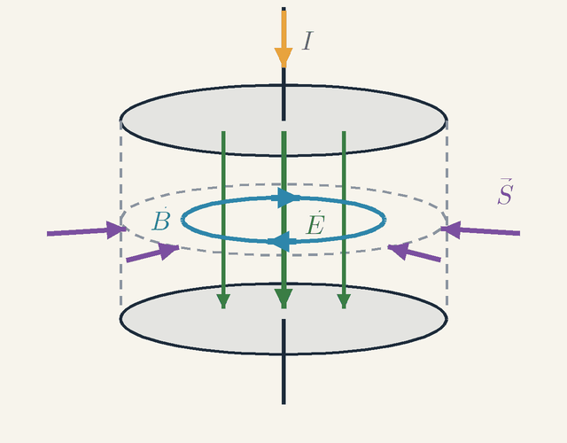
Figure 4. A circular-plate capacitor while it charges. The current I makes the field E in the gap grow, the growing field makes a magnetic field B round the axis, and the energy flux S points inward all round the rim: the field energy enters from the sides. Not to scale.Legend
I
Current in the leads, flowing down onto the upper plate.
A
E
Electric field in the gap, pointing down and growing as the plates charge.
N/C
B
Magnetic field made by the growing E, circling the axis clockwise seen from above.
T
S
Energy flux (Poynting vector), E×B/μ0: energy per second per square metre, inward all round the rim.
W/m2
Figure 4 shows an air capacitor with circular plates while it charges. The current I in the leads flows down onto the upper plate, so the plates gain charge and the field E in the gap, pointing down, grows.
A changing electric field makes a magnetic field, just as a current does. Maxwell called the term ε0dΦE/dt the displacement current, where ΦE is the electric flux through the gap. Between the plates it is exactly equal to the current I in the wires, since ε0AdE/dt=dQ/dt. So a magnetic field B circles the axis inside the gap, in the same sense as it circles the leads: clockwise seen from above, by the right-hand rule for a downward current.
Now look at the rim of the gap. There E points down and B runs along the circle. The energy flux, or Poynting vector, S=E×B/μ0, is perpendicular to both, and the right-hand rule makes it point radially inward at every point of the rim. The field energy flows in from the surrounding space, through the open sides of the gap, not along the wires. Adding up S over the whole rim gives exactly the rate at which the energy 21ε0E2 per cubic metre grows inside.
Forces from energy
The energy also gives the force between the plates, without needing to know how the charge is spread over them. The method, called virtual work, imagines a tiny movement and asks how the energy changes.
Isolate the charged capacitor, so that Q cannot change, and pull one plate away by a small distance dz. The work you do, Fdz, must equal the rise in stored energy Q2/(2C). For a gap z, 1/C=z/(ε0A), so the stored energy is Q2z/(2ε0A), which grows in proportion to z. Its rate of change with z is the force: F=2ε0AQ2=21QE Why ½ and not simply QE? Each plate makes half the field in the gap, and a plate is pushed only by the other plate's half. The method works for any shape once C is known as a function of position.
A number shows how weak this force is. Built as an air capacitor with a 1 mm gap, the animation's 100 µF would need a plate area A=Cd/ε0≈1.1×104m2, about one and a half football pitches. At 12 V the plates would attract with F=W/d=7.2N, a pressure of only 6.4×10⁻⁴Pa. That pressure equals the energy density u of the field: force per square metre and energy per cubic metre have the same units, and here the same value.
Dielectrics
An insulator in the gap raises the capacitance by its relative permittivity εr. The cause is polarisation. In the field, the insulator's molecules stretch or turn so that their positive and negative charges separate slightly. Inside the material these shifts cancel out, but they leave bound charges on its two faces: negative next to the positive plate, positive next to the negative one. The bound charges make a field opposite to that of the free charge on the plates, and cancel part of it.
At fixed charge Q, the field in the gap, and with it the voltage, falls by the factor εr, so C=Q/V rises by εr. At fixed voltage, εr times as much charge flows onto the plates. Either way, C=ε0εrA/d.
Worked problem: charging in two steps
Losing half the energy is the price of charging from a fixed voltage; it is not a law of nature. Take the animation's capacitor and resistor, C=100μF and R=10kΩ, so τ=1s, and charge to 12 V in two stages: first from a 6 V supply until full, then from the 12 V battery. How much heat is produced in all?
Stage one is the animation at half the voltage. The supply moves C⋅6V=0.6mC through 6 V and so supplies 3.6 mJ. Of this, 21⋅10−4⋅62=1.8mJ is stored and the other 1.8 mJ becomes heat: half, as before.
Stage two starts at VC=6V, so only the difference, 6 V, drives current through the resistor. With x0=6 and x∞=12 in the relaxation law, in volts and milliamperes, VC=12−6e−t/τ,I=0.6e−t/τ The current starts at only 0.6 mA, and the heat is ∫0∞I2Rdt=R(6V)2⋅2τ=10436⋅0.5J=1.8mJ
The energy bookkeeping agrees. In this stage the battery moves another 0.6 mC through 12 V and supplies 7.2 mJ, while the stored energy rises from 1.8 to 7.2 mJ, by 5.4 mJ. The difference is again 1.8 mJ of heat.
In total 3.6 mJ is lost instead of 7.2 mJ. The general rule is that each step of size ΔV turns 21C(ΔV)2 into heat, whatever voltage it starts from, so N equal steps lose 21CV02/N: only 0.6 mJ for twelve steps of 1 V. A supply ramped up slowly compared with τ loses almost nothing, which is the idea behind adiabatic charging in low-power electronics. The price is time, since each step needs about 5τ to finish.
Limits of the simple model
The formula C=ε0εrA/d assumes a uniform field that stops sharply at the edges of the plates. In reality the field bulges outward at the edges, and this fringing field adds capacitance: about 4 % for discs 10 cm across and 1 mm apart, and 0.6 % at 0.1 mm.
Real insulators also leak a little current, and every one breaks down, suddenly conducting with a spark, above a field called its dielectric strength. For dry air that is about 3 MV/m, which caps the energy density of an air gap at 21ε0E2≈40J/m3. Polymer films withstand hundreds of megavolts per metre and store a few MJ/m³, still hundreds of times less than a lithium-ion battery. Capacitors win on speed, not on storage.
The circuit model also assumes quasi-static change: slow enough that the field everywhere keeps pace with the charge. Two effects break it at high frequency. First, real parts have inductance: a small ceramic capacitor has about a nanohenry in its leads and plates, so a 100 nF part resonates near 16 MHz and behaves like a coil above that.
Second, even ideal plates fail, because the changing magnetic field of Figure 4 induces an electric field of its own, which alters E across the gap. At 1 GHz the field at the rim of plates of 1 cm radius is about 1 % weaker than at the centre, and near 11 GHz such plates become a resonant cavity.
Last, charge is not infinitely divisible. One extra electron raises the voltage of a 1 fF capacitor by only 0.16 mV. But the energy needed to add one electron grows as the capacitance shrinks, and below a few attofarads it exceeds the thermal energy at room temperature, about 0.026 eV. Electrons can then enter only one at a time, an effect called the Coulomb blockade, which single-electron transistors exploit.
Where this leads
Electric Current and Resistance explains the resistor that sets τ, and DC Circuits and Ohm's Law the loop rule behind the charging law. In Electric Power and Energy at Home, capacitors on an alternating voltage store and return energy every cycle. Electromagnetic Induction adds the inductor: together with a capacitor it obeys Lq¨+q/C=0, the equation of Simple Harmonic Motion with ω=1/LC, and resistance turns it into a case of Damping and Resonance. The displacement current in the gap is the term that completes the field equations and predicts Electromagnetic Waves, and the exponential with its time constant returns in Radioactivity and Half-Life.
Key formulas
Charge and voltage of a capacitor
Q=CV
The charge on each plate is proportional to the voltage between them, because doubling the charge doubles the field and therefore the work per coulomb. The constant of proportionality, the capacitance C, is the charge stored per volt and depends only on the geometry and the insulator. Q is the charge on one plate, not the total, which is zero.
Symbols
Q
charge on the positive plate (the other carries −Q)
C
C
capacitance
F
V
voltage between the plates
V
When it holds: Holds for any pair of conductors with vacuum or an ordinary insulator between them. It fails for ferroelectric materials, whose permittivity depends on the field, and above the breakdown voltage.
Example: The animation's 100 µF capacitor on 12 V: Q=10−4⋅12=1.2×10⁻³C=1.2mC.
Capacitance of a parallel-plate capacitor
C=dε0εrA
Gauss's law gives the field between the plates, E=Q/(ε0εrA), and the voltage is V=Ed; dividing Q by V gives the formula. Larger plates spread the charge thinner, a narrower gap shortens the path across it, and a dielectric's polarisation cancels part of the field. All three lower the voltage per coulomb and so raise C.
Symbols
C
capacitance
F
ε0
permittivity of free space, about 8.85×10⁻¹²F/m
F/m
εr
relative permittivity of the insulator (1 for vacuum)
A
area of each plate facing the other
m2
d
distance between the plates
m
When it holds: Assumes a uniform field, so the gap must be much smaller than the plates. The field bulging out at the edges adds a correction that grows with the gap: about 4 % for discs 10 cm across and 1 mm apart.
Example: Plates of 1 cm² with a 0.5 mm air gap: C=8.85×10−12⋅10−4/(5×10−4)≈1.77pF.
Energy stored in a capacitor
W=21CV2=21QV
Charging means carrying charge across a voltage that rises in proportion to it, from zero to V, so the work is the area of the triangle under the voltage–charge line, half of QV. With Q=CV the same energy is 21CV2, or Q2/(2C). It is stored in the electric field between the plates and returned when the capacitor discharges.
Symbols
W
energy stored
J
C
capacitance
F
V
voltage between the plates
V
Q
charge on the positive plate
C
When it holds: Holds for any capacitor whose capacitance does not depend on its charge. It is the energy stored, not the energy the source supplied: charged from a fixed voltage through a resistor, the source supplies QV and the other half is lost as heat.
Example: The animation's capacitor at 12 V: W=21⋅10−4⋅122=7.2mJ, the same as 21⋅1.2mC⋅12V.
Time constant of an RC circuit
τ=RC
A larger resistance lets the charge in more slowly, and a larger capacitance needs more charge for each volt, so both lengthen the charging. Their product is a time: ohms times farads is (V/A)(C/V)=C/A=s. After one time constant the capacitor has 63 % of its final voltage, and the current has fallen to 37 % of its initial value.
Symbols
τ
time constant
s
R
resistance in series with the capacitor
Ω
C
capacitance
F
When it holds: For one resistor and one capacitor in series, with constant values; in a larger network, R is the resistance the capacitor sees. Kilo-ohms times microfarads give milliseconds.
Example: In the animation, τ=104Ω⋅10−4F=1s; 2.2 kΩ with 47 µF gives about 0.10 s.
Capacitor voltage while charging
VC=V0(1−e−t/RC)
This solves the loop equation Rdq/dt+q/C=V0 for a capacitor that is empty at t=0. The voltage rises at a rate proportional to what is still missing, V0−VC, so the gap closes by the same factor e in every time constant: fast at first, then ever more slowly. The voltage never jumps, because a jump would need an infinite current.
Symbols
VC
voltage across the capacitor at time t
V
V0
battery voltage, the final value of VC
V
e
Euler's number, about 2.718, the base of natural logarithms
t
time since the switch was closed
s
R
resistance in series
Ω
C
capacitance
F
When it holds: For a capacitor that starts empty and is charged from a constant voltage through a constant resistance. Starting from V1 instead, VC=V0−(V0−V1)e−t/RC; discharging from V1, VC=V1e−t/RC.
Example: In the animation, at t=τ=1s, VC=12(1−e−1)≈7.6V; at 2 s, 12(1−e−2)≈10.4V.
Charging current
I=(RV0)e−t/RC
The current is the voltage left across the resistor, V0−VC, divided by R. It starts at its largest value, V0/R, as if the empty capacitor were a plain wire, and dies away exponentially as the capacitor fills. Since I=CdVC/dt, it follows the slope of the voltage curve, and its area over time is the charge stored.
Symbols
I
current in the circuit at time t
A
V0
battery voltage
V
R
resistance in series
Ω
e
Euler's number, about 2.718
t
time since the switch was closed
s
C
capacitance
F
When it holds: For charging from empty through a constant resistance; a discharge follows the same law with the current reversed. In a real circuit a little inductance rounds off the jump at the start.
Example: In the animation, I0=12/104A=1.2mA, and at t=τ, I=1.2e−1≈0.44mA.
Energy density of the electric field
u=21ε0εrE2
Writing 21CV2 with C=ε0εrA/d and V=Ed gives 21ε0εrE2 times the volume Ad of the gap. The energy can therefore be counted as spread through the field, an amount u in every cubic metre. The result is general: it holds for any electric field, not only between plates.
Symbols
u
energy per unit volume of the field
J/m3
ε0
permittivity of free space
F/m
εr
relative permittivity of the medium
E
electric field strength
V/m
When it holds: In vacuum (εr=1) it holds for any field, even a rapidly changing one; in a linear dielectric, for a static or slowly changing field. Breakdown sets a ceiling: in dry air, at about 3 MV/m, u cannot exceed about 40J/m3.
Example: 12 V across a 1 mm air gap gives E=1.2×10⁴V/m and u=21⋅8.85×10−12⋅(1.2×104)2≈6.4×10⁻⁴J/m3.
Glossary
Capacitor
Two conductors separated by an insulator, used to store separated charge and, with it, energy. When charged, one conductor carries +Q and the other −Q, so the device as a whole stays neutral.
Capacitance
The charge stored per volt, C=Q/V, measured in farads. It depends only on the size, shape and spacing of the conductors and on the insulator between them, not on how much charge they hold.
Parallel-plate capacitor
Two flat plates of area A a small distance d apart. The field between them is nearly uniform, E=V/d, and the capacitance is C=ε0εrA/d, accurate when the gap is much smaller than the plates.
Dielectric
An insulator placed in the gap. It multiplies the capacitance by its relative permittivity εr (about 2.2 for polypropylene, 80 for water) and usually withstands a stronger field than air.
Dielectric polarisation
The slight shift of the charges inside the molecules of a dielectric placed in a field. It leaves bound charges on the dielectric's faces, opposite in sign to those on the neighbouring plates, which partly cancel the field.
Dielectric breakdown
The sudden conduction of an insulator when the field exceeds its dielectric strength, about 3 MV/m (3 kV per millimetre) in dry air. It sets the highest voltage a capacitor can take.
RC circuit
A resistor and a capacitor in series. Through it a capacitor charges or discharges exponentially, at a pace set by the product RC.
Time constant
The time τ=RC that sets the pace of charging and discharging. After τ a charging capacitor has 63 % of its final voltage, after 5τ more than 99 %.
Exponential decay
A change whose rate is proportional to what is left, so that equal times multiply it by equal factors: e−1≈0.37 per time constant, one half per τln2. The charging current and the voltage of a discharging capacitor both follow it.
Field energy
The energy of a charged capacitor, counted as stored in the electric field between the plates with density u=21ε0εrE2. Added up over the volume of the gap, it gives 21CV2.
Displacement current
The quantity ε0dΦE/dt, ε0 times the rate of change of the electric flux ΦE, which acts like a current in producing a magnetic field. In the gap of a charging capacitor it equals the current in the wires, although no charge crosses.
Quantities
Q
Charge
C
The charge on the positive plate; the other plate carries −Q. In the animation it reaches CV0=1.2mC.
V
Voltage
V
The potential difference between the plates, the work per coulomb to carry charge from the negative plate to the positive one. In the circuit, VC is the capacitor's voltage and V0 the battery's.
C
Capacitance
F
The charge stored per volt, Q/V. Since 1F=1C/V is huge, practical values are given in µF, nF and pF. For parallel plates of area A (in m²) a distance d (in m) apart, C=ε0εrA/d.
ε0
Vacuum permittivity
F/m
The constant of electrostatics in SI units, about 8.85×10⁻¹²F/m. It fixes the capacitance of a gap filled with vacuum.
εr
Relative permittivity
The factor by which an insulator raises the capacitance above that of vacuum, also called the dielectric constant: 1 for vacuum, 1.0006 for air, about 80 for water.
E
Electric field
V/m
The force per unit charge on a small test charge (1 V/m = 1 N/C). Between parallel plates it is uniform, E=V/d, and proportional to Q, like the purple arrows of the animation. Its energy density is u=21ε0εrE2 (in J/m³).
W
Stored energy
J
The work done to separate the charges, 21CV2, given back on discharge; 7.2 mJ for the fully charged capacitor of the animation.
I
Current
A
The charge flowing per second, dq/dt, the same in both wires. While charging, I=(V0−VC)/R.
R
Resistance
Ω
The resistance in series with the capacitor, which limits the current and so sets the pace of charging; 10 kΩ in the animation.
τ
Time constant
s
The product RC: the time for the charging current to fall to 37 % of its initial value, 1 s in the animation. In the charging laws, t (in s) is the time since the switch was closed.
Quiz
Beginner What does a capacitor do in a circuit?
It produces energy, like a battery
It lets a steady current flow through it forever
It destroys charge
It stores separated charge, and with it energy
Show answer
Answer: D. It stores separated charge, and with it energy
A capacitor stores equal and opposite charges on its plates and the energy of the field between them. It does not produce energy; it only stores what the circuit gives it.
Beginner An empty capacitor is connected to a battery through a resistor. How does the current change?
It stays the same until the capacitor is full
It is largest at the start and then decreases
It starts at zero and grows
It keeps changing direction
Show answer
Answer: B. It is largest at the start and then decreases
Like water flowing into a tank from below, the flow is fastest while the tank is empty. As the capacitor fills, its charge pushes back against the battery and the current fades.
Beginner When a capacitor has been charged by a battery, what is on its two plates?
Equal amounts of positive and negative charge
Positive charge on both plates
Negative charge on both plates
No charge at all
Show answer
Answer: A. Equal amounts of positive and negative charge
Electrons are moved from one plate to the other, leaving one plate +Q and the other −Q.
Intermediate How much charge is stored on a 47 µF capacitor connected to 10 V?
4.7 µC
47 µC
470 µC
4.7 mC
Show answer
Answer: C. 470 µC
Q = C·V = 47 × 10⁻⁶ F × 10 V = 4.7 × 10⁻⁴ C = 470 µC.
Intermediate The gap between the plates of a parallel-plate capacitor is doubled, with the plate area unchanged. What happens to the capacitance?
It halves
It doubles
It quadruples
It does not change
Show answer
Answer: A. It halves
C = ε₀·A / d is inversely proportional to d, so doubling the gap halves the capacitance.
Intermediate What is the time constant of a circuit with R = 2 kΩ and C = 500 µF?
0.25 s
1 s
4 s
1000 s
Show answer
Answer: B. 1 s
τ = R·C = 2000 Ω × 500 × 10⁻⁶ F = 1 s. Ohms times farads gives seconds.
Advanced A capacitor charges from zero through a resistor. What fraction of the final voltage has it reached after 3τ?
63 %
86 %
37 %
95 %
Show answer
Answer: D. 95 %
V_C / V₀ = 1 − e⁻³ ≈ 1 − 0.050 = 0.95. After τ it is 63 %, after 2τ about 86 %.
Advanced A capacitor is charged from zero to V₀ by a battery V₀ through a resistor R. What fraction of the energy delivered by the battery ends up stored in the capacitor?
All of it
It depends on R
Exactly half
About 63 %
Show answer
Answer: C. Exactly half
The battery delivers Q·V₀ = C·V₀², the capacitor stores ½·C·V₀², and the other half is dissipated in the resistor, whatever the value of R.
 Physics Tutor