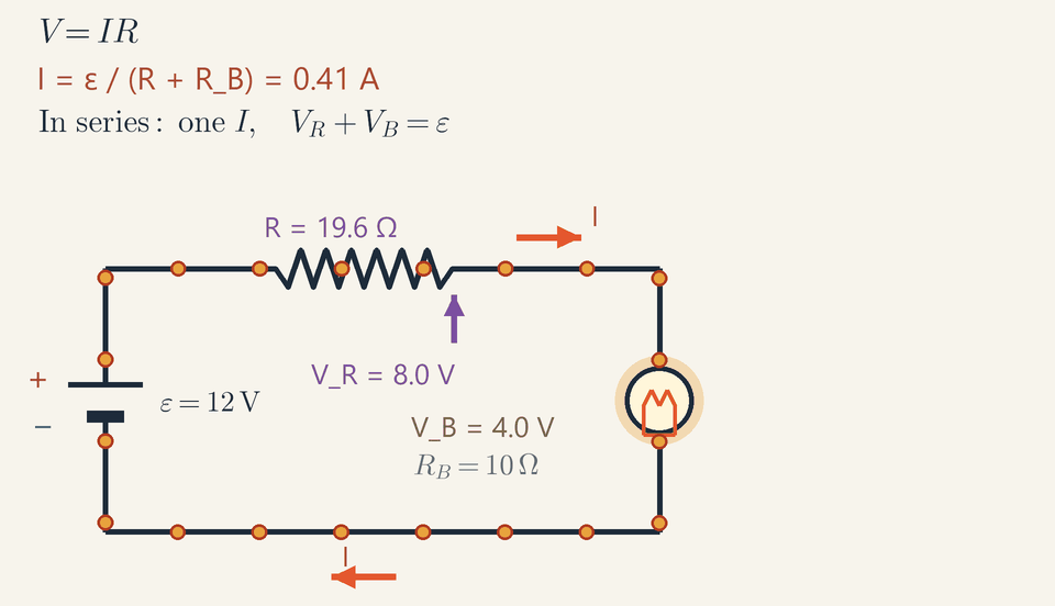
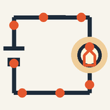
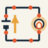
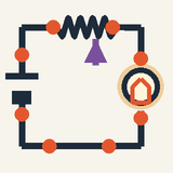
A circuit is a closed loop: a battery, wires and a device. Open the loop anywhere and the current stops everywhere.
The battery pushes the charges already in the wires; its voltage is the energy per coulomb: 9 V gives each coulomb 9 joules.
Current = voltage ÷ resistance: more resistance means less current all around the loop and a dimmer bulb.
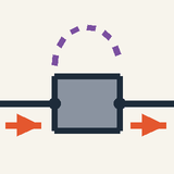
In series there is one path: the same current flows through every part, and one break stops them all.
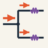
In parallel each branch gets the full voltage and works on its own, as in house wiring.
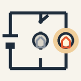
Press a switch and a bulb lights. An electric circuit is a closed loop that charge can travel around: a battery, some wires and something that uses energy, such as a bulb. Open the loop anywhere, with a switch say, and the flow stops everywhere at once.
Step 1: the battery. Chemical reactions inside it keep one terminal positive and the other negative. It does not create charge (the wires are already full of it); it pushes that charge around the loop. Its voltage tells you how much energy each coulomb carries from one terminal to the other: a 9 V battery gives every coulomb 9 joules.
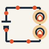
Step 2: resistance. A bulb or a resistor makes it harder for charge to get through, like a narrow section in a water pipe. More push gives more current; more resistance gives less. So current = voltage ÷ resistance (Ohm's law). In the animation the purple slider adds resistance: the orange dots slow down all around the loop, not just inside the resistor, and the bulb dims.
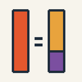
Step 3: one path (series). When parts are lined up one after another, the same current flows through each of them, their resistances add up and they share the battery's voltage. If one bulb in a series string breaks, the loop is open and every bulb goes out.
Step 4: several paths (parallel). When each part has its own branch across the battery, each gets the full voltage and works on its own. Homes are wired this way, so switching off a lamp does not stop the fridge.
The dots move at the same pace everywhere: charge is not used up. The bulb takes energy from the charges, not the charges themselves.
Check yourself: a 6 V battery drives a current through a 3 Ω resistor. What is the current? (Answer: 2 A.)
Intermediate
Key ideas
Ohm's law: V=IR. A volt is a joule per coulomb, an ampere a coulomb per second; resistance is measured in ohms.
In series: one path, the same current I everywhere, R=R1+R2, and the voltage drops add up to ε.
In parallel: each branch gets the full voltage, the branch currents add and 1/R=1/R1+1/R2.
Example: 12 V across 5 Ω + 10 Ω gives I=0.80A, VR=4.0V and VB=8.0V.
Current, voltage and resistance
A bulb lights as soon as its switch is closed, yet the electrons in its copper wires drift at a fraction of a millimetre per second. A circuit is a closed path of conductors, already full of mobile charges (free electrons in a metal); the battery does not supply them but keeps them moving. The current I is the charge passing a point per second, I=Q/t, in amperes: 1A=1C/s. By convention it flows the way positive charge would, from the + terminal round the circuit to the − terminal, as the dots in the animation do; the electrons in a metal drift the opposite way, which is the same current.
The voltage V between two points is the energy each coulomb gains or loses between them (1V=1J/C): a difference of electric potential φ, like a difference in height. The energy per coulomb that a battery supplies is its electromotive force (emf) ε; the animation's 12 V battery gives every coulomb 12 J. The resistance R, in ohms (1Ω=1V/A), is the voltage needed per ampere. To measure them, an ammeter is placed in series and a voltmeter in parallel.
Ohm's law
For a metal at a steady temperature, the current is proportional to the voltage. Ohm's law writes this as V=IR with R constant: double the voltage and the current doubles. The graph of V against I is a straight line through the origin with slope R, and such components are called ohmic. A filament lamp is not, because its resistance rises about tenfold as it heats up, and neither is a diode, which conducts one way only.
The resistance of a uniform wire grows with its length L and falls with its cross-sectional area A: R=AρL where the resistivity ρ depends on the material. For copper ρ=1.7×10⁻⁸Ωm, so a metre of 1 mm² wire has only 0.017 Ω: connecting wires can usually be treated as resistance-free next to a 10 Ω bulb.
Series, parallel and power
Components in series lie one after another on a single path, so they carry the same current, and their voltages add: IR1+IR2=I(R1+R2). Components in parallel are connected across the same two points, so they share the same voltage, and their currents add. Each branch is one more path, so the conductances G=1/R, in siemens (S), add, and the group conducts better than any branch alone:
Rseries=R1+R2
Rparallel1=R11+R21
For two resistors in parallel this gives R1R2/(R1+R2), less than the smaller one. A larger network is reduced step by step, each series chain or parallel group replaced by its equivalent. Finally, each coulomb falling through a voltage V gives up V joules, and I coulombs pass per second, so the power, in watts, is P=VI=I2R=RV2 In series, where I is shared, the larger resistance takes more power; in parallel, where V is shared, the smaller one does.
Worked example: the circuit in the animation
The battery has ε=12V and the bulb RB=10Ω, treated as ohmic; the purple slider takes the rheostat from 5 Ω to 20 Ω and back every 8 s. At the start, with R=5Ω, I=R+RBε=5+1012=0.80A VR=0.80⋅5=4.0V,VB=0.80⋅10=8.0V
These are the I, VR and VB readouts, and the drops add up to 12 V. The bulb converts PB=8.0⋅0.80=6.4W and the rheostat 3.2 W, together the εI=9.6W the battery delivers. Halfway through the cycle, at R=20Ω, the current is 12/30=0.40A, VR=8.0V and VB=4.0V. The shares have swapped: in series each component takes a share of the voltage proportional to its resistance. The bulb's power falls fourfold, to 1.6 W, and its glow shrinks.
The two red I arrows, on the top wire just before the bulb and on the bottom wire after it, always have the same length: the bulb takes energy from the charges, not the charges themselves. The dots slow down all round the loop at once, not only in the rheostat.
Worked example: headlamps on a car battery
A car's two headlamps, each 2.4 Ω when hot, are in parallel across its 12 V battery. What current flows, and what changes when the 1.2 Ω rear-window heater is switched on too?
Each lamp has the full 12 V across it, so it draws 12/2.4=5.0A and converts 12⋅5.0=60W; together they draw 10 A, like a single 1.2 Ω resistor. The heater adds a third branch of 12/1.2=10A, so the battery now supplies 20 A, and indeed Rparallel1=2.41+2.41+1.21=0.60Ω1 gives 12/0.60=20A.
Ideally the lamps do not notice the heater. In practice they dim slightly: the battery's small internal resistance r, about 0.02 Ω, costs 20⋅0.02=0.4V at 20 A, and some 3 V when the starter motor draws about 150 A, so the lamps dim while the engine cranks.
Following the potential around the loop
Take the − terminal as zero potential and follow the current: the potential jumps up 12 V in the battery, stays almost constant along the wires, falls by VR in the rheostat and by VB in the bulb, and is back at zero. The step up and the two steps down cancel, so VR+VB=ε, the series rule shown in the animation.
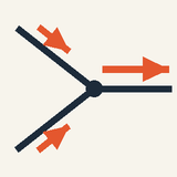
Two rules extend this to any network. No charge piles up at a junction, so, counting inflowing currents as positive and outflowing ones as negative, ∑I=0at a junction And once round any closed loop, the emfs passed equal the drops in the resistors, each signed by the direction of travel: ∑ε=∑IRaround a loop
These are Kirchhoff's rules, expressing conservation of charge and of energy. For the animation's loop the second gives 12=5I+10I at the start, the 0.80 A again.
Common mistakes
A bulb does not use up current: 0.80 A goes in and 0.80 A comes out. It uses up energy, 8 J from every coulomb.
A battery gives a nearly fixed voltage, not a fixed current: the same 12 V drives 0.80 A through 15 Ω but 0.40 A through 30 Ω.
A resistor added in parallel lowers the total resistance and raises the battery current: two 10 Ω bulbs in parallel make 5 Ω, not 20 Ω.
Electrons do not race round the circuit: carrying 0.80 A in a 1 mm² copper wire they drift at about 0.06 mm/s, almost five hours per metre. The bulb lights at once because the push reaches all of them within nanoseconds.
A short circuit means a huge current, not none: across a car battery with 0.02 Ω inside, 12/0.02=600A, enough to melt a thin wire.
Where you meet it
A torch is a cell, a switch and a lamp in series; a house is wired in parallel, so that every appliance gets the full mains voltage and switches on its own. Volume knobs and fuel gauges are rheostats or voltage dividers, and strain gauges and thermistors are resistors whose R changes with force or temperature. The same rules lie behind the RC charging in Capacitors, and they return in Electric Power and Energy at Home (kilowatt-hours and fuses) and Magnetic Fields of Magnets and Currents.
Advanced
Key ideas
Lumped elements are described only by terminal current and voltage: valid while no changing flux threads the circuit.
Kirchhoff: ∑I=0 at a node (charge conservation) and ∑V=0 around a loop (∮E⋅dl=0).
Seen from two terminals, any linear network acts like one emf plus one series resistance (Thévenin); a real battery gives ε−Ir.
A source delivers εI, a resistor dissipates I2R; a load on internal resistance r gets the most power at R=r (50 % efficiency).
The energy reaches the resistor through the field around the wires, flowing in through its sides, not inside the copper.
From fields to lumped elements
Circuit theory is a deliberate simplification, and it pays to know exactly what it throws away. A working circuit is full of electric and magnetic fields, yet we describe it with a handful of numbers. This section says how that reduction works and when it is allowed.
The example throughout is the circuit of the animation: a 12 V battery, a rheostat (a resistor whose value can be varied) and a bulb, all in one loop. The rheostat's resistance R swings between 5 Ω and 20 Ω every 8 seconds, and the bulb is treated as a fixed resistance RB=10Ω.
Each element, whether a cell, a resistor or a bulb, is treated as a box with two terminals, a and b. What happens inside is ignored; all that matters is the current I through the element and the voltage between its terminals, Vab=φa−φb=∫abE⋅dl where φ is the electric potential and E the electric field. For this to be a single number, the integral must not depend on the path taken from a to b. It does not, as long as the field outside the element is electrostatic, because the integral of such a field round any closed loop is zero, so two paths with the same ends give the same result. All the detail inside, the field pattern in a resistor or the chemistry of a cell, is condensed into one number per element: a resistance R or an emf ε.
Two conditions make this lumped description exact. First, no changing magnetic flux may thread the space between the elements; otherwise Faraday's law adds an induced emf and ∮E⋅dl is no longer zero there. Second, charge must not build up anywhere, so that the current entering an element equals the current leaving it. A DC circuit meets both once the brief switching transient is over.
One question remains: how does the field know to follow every bend of the wire? It is produced by charges on the surfaces of the wires and components, which rearrange within nanoseconds of closing the switch until the field inside each wire points along it. In copper the field needed is tiny. Take the animation's largest current, 0.80 A, in a wire of cross-section 1 mm². The current density, the current per unit area, is J=0.80/10−6=8×105A/m2. Copper's resistivity ρ, the field needed per unit current density, is 1.7×10⁻⁸Ωm, so E=ρJ=1.7×10−8⋅8×105≈0.014V/m Each metre of wire uses up only about 0.014 V, so almost all of the 12 V falls across the rheostat and the bulb.
Kirchhoff's rules from conservation laws
Two rules solve every DC circuit, and each is a conservation law: the junction rule expresses conservation of charge, the loop rule conservation of energy. Seeing where they come from also shows when they would fail.
Let J be the current density: a vector pointing along the flow, whose size is the current per unit area, in A/m². The current leaving a closed surface is ∮J⋅dA, where dA is a small patch of the surface pointing outward. Charge is neither created nor destroyed, so this outflow equals the rate at which the charge inside decreases. In a steady state the charge inside stays constant, so ∮J⋅dA=0 Now draw the surface tightly round a junction. Only the wires pierce it, each contributes its own current, and the result is the junction rule, ∑I=0, with currents leaving counted positive and currents arriving negative.
The loop rule needs one more ingredient. An electrostatic field alone cannot keep charge circulating, because its integral round a loop is zero: it does as much work against the charges on one part of the loop as it does for them on another. Inside a cell a second, non-electrostatic force acts. Call it f, the force per unit charge; it is chemical in origin and pushes charge from the − terminal to the + terminal, against the electrostatic field. Its integral across the cell is the emf, ε=∫−+f⋅dl the work it does on each coulomb that passes through. In an ideal cell, with no internal resistance, f and the electrostatic field cancel inside, so the emf equals the voltage between the terminals.
Outside the cells only the electrostatic field acts, and ∮E⋅dl=0 means that the potential has one value at each point: start anywhere, go round a loop, and you arrive back at the same potential. The rises across the cells must therefore equal the drops across everything else. That is the loop rule, an energy balance for each coulomb that goes round.
A resistor needs a law of its own, and it comes from the material. Locally, J=σE, where σ is the conductivity and ρ=1/σ the resistivity. In a uniform wire of length L and cross-section A the field is uniform, so the voltage is V=EL and the current I=JA=σEA. Eliminating E gives Ohm's law, V=IR, with R=ρL/A.
Now apply the rules to the animated loop. It has no branches, so one current I flows everywhere. Going round, the battery raises the potential by ε, and the rheostat and the bulb lower it by IR and IRB: ε−IR−IRB=0⇒I=R+RBε With ε=12V and RB=10Ω the current runs between 0.80 A at R=5Ω and 0.40 A at R=20Ω.
The familiar combination rules follow at once. Elements in series share one current, so their voltages add and so do their resistances. Elements in parallel share one voltage, so their currents add and so do the reciprocals of their resistances.
For a larger network the rules always give enough equations. Suppose it is connected and has n junctions and b branches, a branch being a stretch of circuit between two junctions with its own current; there are then b unknown currents. The junction rule gives n−1 independent equations (the last one is the sum of the others, since every branch current leaves one junction and enters another), and the loop rule gives one for each of the b−n+1 independent loops: exactly b equations in all.
Solving the loop on a V–I graph
A graph can solve the loop without algebra, and it keeps working when a component does not obey Ohm's law. The idea is to draw, on the same axes, what the bulb allows and what the rest of the circuit allows.
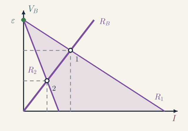
Figure 1. The bulb's line VB=RBI and the load line VB=ε−RI of the rest of the circuit, drawn for the rheostat at its two ends, R1 and R2 (the shaded fan holds the settings in between). Each crossing, 1 or 2, is the operating point for that setting.Legend
I
Current through the bulb, the same all round the loop.
A
VB
Voltage across the bulb.
V
ε
Emf of the battery: where every load line meets the voltage axis.
V
RB
Resistance of the bulb: the slope of its line.
Ω
R1
Rheostat at the low end of its range: a shallow load line of slope −R1, reaching the current axis at ε/R1.
Ω
R2
Rheostat at the high end of its range: a steeper load line of slope −R2.
Ω
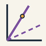
Figure 1 has the current I along the horizontal axis and the bulb's voltage VB up the vertical one. The bulb's own rule, VB=RBI, is the straight line through the origin labelled RB; its slope is RB=10Ω. Every state the bulb can be in lies on this line. (In the animation's expert panel the same line is drawn dashed, and a point slides along it between (0.40 A, 4.0 V) and (0.80 A, 8.0 V).)
The rest of the circuit, battery and rheostat together, makes a second demand. Seen from the bulb, the battery supplies ε and the rheostat takes IR of it, so what is left appears across the bulb: VB=ε−RI This is the load line. It starts on the voltage axis at the dot labelled ε, 12 V: with no current there is no drop across the rheostat, so the bulb would feel the whole emf. It then falls with slope −R and reaches the current axis at ε/R, the current the battery would drive if the bulb were replaced by a wire.
The bulb must obey its line and the circuit must obey the load line, so the actual state of the circuit, its operating point, is where the two cross. Setting them equal, RBI=ε−RI, gives back exactly the loop rule: the picture and the algebra solve the same equation.
Now follow the rheostat. The figure draws the load line for the two ends of its range, R1=5Ω and R2=20Ω, and the shaded fan between them holds every setting in between. As R grows from R1 to R2, the load line pivots about its fixed end at ε and swings down, from the shallow line R1, which would reach the current axis at 2.4 A, to the steep line R2, which stops at 0.60 A. Its crossing with the bulb's line slides down from point 1, at (0.80 A, 8.0 V), to point 2, at (0.40 A, 4.0 V).
The method shows its real strength with components that are not ohmic. A real filament's curve bends upward as it heats, and a diode's is a sharp knee; neither has a single resistance, so the formula for I no longer applies. The crossing with the load line is still the answer, found graphically or numerically.
The bulb's power over one cycle
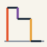
The bulb's brightness follows its power, and the animation's graph of that power against time holds a surprise. With I=ε/(R+RB), the bulb receives PB=I2RB=(R+RB)2ε2RB which runs from 6.4 W at R=5Ω down to 1.6 W at R=20Ω.
The rheostat follows a cosine, R=12.5−7.5cos(2πt/T) in ohms, with period T=8s, but the power is no copy of it. Because PB goes as the inverse square of R+RB, it drops quickly from its peak and lingers near its minimum. At t=2s the rheostat is halfway, at 12.5 Ω, yet PB=122⋅10/22.52≈2.8W, not the 4.0 W midway between the extremes, and it stays below 4 W for about two thirds of each cycle. The area under the curve, about 27 J per 8 s cycle, is the energy the bulb converts into heat and light.
Networks and Thévenin's theorem
A large network would be hopeless to analyse if every change meant starting again from scratch. Linearity saves the day: it lets a whole network be replaced by two numbers.
With ohmic elements every one of Kirchhoff's equations is linear in the currents and the emfs. Two consequences follow. The first is superposition: the currents produced by several sources acting together are the sums of the currents each source would produce on its own. The second is Thévenin's theorem: any network of sources and resistors, seen from two of its terminals, behaves exactly like one emf εTh in series with one resistance RTh. The reason is that, by linearity, the voltage at the terminals is a straight-line function of the current drawn from them, V=εTh−RThI, and a straight line needs only an intercept and a slope.
Both numbers are easy to find. The emf εTh is the voltage across the open terminals, when no current is drawn. The resistance RTh is the resistance between the terminals with every ideal emf replaced by a wire.
Maximum power from a source
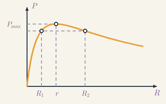
Which load takes the most power from a given source? The answer, called matching, matters from radio receivers to the animation itself. The simplest real source is a battery: an ideal emf ε in series with an internal resistance r, already in Thévenin form. Drawing a current I makes its terminal voltage sag to ε−Ir. A load R carries I=ε/(R+r) and so receives P=I2R=(R+r)2ε2R
Figure 2. Power drawn by a load R from a source of emf ε and internal resistance r: zero at R=0, a single peak Pmax at R=r, then a slow decline. The loads R1 and R2, with R1R2=r2, draw the same power.Legend
R
Resistance of the load.
Ω
P
Power the load draws from the source.
W
r
Internal resistance of the source; the peak lies at R=r.
Ω
Pmax
Highest power the source can deliver to a load, ε2/(4r).
W
R1
A load smaller than r.
Ω
R2
A load larger than r, with R1R2=r2; it draws the same power as R1.
Ω
Figure 2 plots this power P against the load R. Look first at the two ends. At R=0 the load is a short circuit: the current is at its largest, ε/r, but there is no voltage across the load, so it takes nothing. As R→∞ the voltage across the load approaches ε, but the current dies away and the power falls to zero again. In between, the curve climbs steeply to a single peak Pmax and then declines slowly.
To locate the peak, differentiate with the quotient rule: dRdP=(R+r)3ε2(r−R) This is positive below R=r, zero at R=r and negative above, so the peak lies at R=r, marked on the axis of Figure 2. There I=ε/(2r) and Pmax=4rε2 while the same amount, I2r, is lost inside the source: at best, half the energy reaches the load.
Whether a design should aim for this peak depends on what the power is for. Matching suits weak signals, such as an antenna's feeding a receiver, where every bit of power counts. Power systems do the opposite and keep R far above r, because the efficiency, the fraction of the output that reaches the load, is R/(R+r), only one half at matching.
The curve also has a less obvious property: equal powers come in pairs. Divide the top and bottom of P by R: P=R+2r+r2/Rε2 Replacing R by r2/R just swaps the first and last terms of the denominator, so P is unchanged. Two loads with R1R2=r2 therefore draw equal power. In Figure 2 they are the two dots on the dashed level line, R1 below r and R2 above it by the same factor, r/R1=R2/r.
This symmetry is hidden in the animation. Look at the circuit from the rheostat's two terminals. By Thévenin, the battery and the bulb in series are a source of 12 V behind RTh=RB=10Ω, so the rheostat is the load R of Figure 2 with r=10Ω. Its power I2R peaks at 122/(4⋅10)=3.6W as the slider passes 10 Ω, and it is 3.2 W at both ends of the range, 5 Ω and 20 Ω, because 5⋅20=102. So while the bulb's power changes fourfold, the rheostat's stays between 3.2 and 3.6 W.
Worked problem: two bulbs on one rheostat
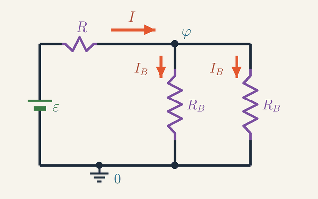
Now put these tools to work on a question with a surprising answer. Two identical bulbs share one rheostat and one battery: should they go in parallel or in series to shine brightest?
Figure 3. The worked problem: battery ε, rheostat R and two identical bulbs RB in parallel. The ground symbol marks the zero of potential and the wire above the bulbs is at φ; the current I splits into two equal currents IB.Legend
ε
Emf of the battery.
V
R
Resistance of the rheostat.
Ω
RB
Resistance of one bulb; the two are equal.
Ω
φ
Potential of the wire above the bulbs, measured from the battery's − terminal.
V
I
Current from the battery through the rheostat.
A
IB
Current in one bulb: half of I, since the bulbs are identical.
A
Figure 3 shows the parallel version: the 12 V battery ε, the rheostat R in the top wire, set to 5 Ω, and two identical 10 Ω bulbs RB side by side between the top and bottom wires. Take the battery's − terminal, marked by the ground symbol, as the zero of potential, and let φ be the potential of the wire that joins the rheostat to the bulbs, at the junction labelled φ. A connecting wire has no resistance, so the whole of that wire is at φ and the whole bottom wire is at 0. Each bulb therefore has φ across it and carries IB=φ/RB.
The current I from the battery passes through the rheostat, which has ε−φ across it, so I=(ε−φ)/R. At the junction I splits into the two bulb currents, so I=2IB by the junction rule. With the numbers in, 512−φ=10φ+10φ⇒φ=6.0V since the right-hand side is φ/5, which makes 12−φ=φ.
So the battery drives I=6.0/5=1.2A, and each bulb takes 0.60 A at 6.0 V, that is 3.6 W, against 6.4 W for a single bulb at the same setting. The battery delivers 12⋅1.2=14.4W, and the rheostat takes 1.22⋅5=7.2W of it, exactly half. Thévenin explains that half: seen from the bulbs, the source is 12 V behind 5 Ω, and the parallel pair, also 5 Ω, is a matched load drawing the maximum, 122/(4⋅5)=7.2W. In series the bulbs make 20 Ω, carry 12/25=0.48A and get only 0.482⋅10≈2.3W each. Parallel wins.
With the rheostat at 20 Ω the roles reverse. In parallel, I=12/25=0.48A, each bulb carries 0.24 A and gets 0.242⋅10≈0.58W. In series, now matched to the source, I=12/40=0.30A and each bulb gets 0.302⋅10=0.90W. Series wins. Since identical bulbs always share the power equally, the brighter connection is simply the one that draws more in total, the one whose resistance lies nearer, by ratio, to the source's. Which connection is brighter depends on the resistance of the source, not on the bulbs alone.
Where the energy really flows
So far P=VI has said how much energy each element takes, not how the energy gets there. At the start of the cycle the battery delivers 12⋅0.80=9.6W and the bulb receives 6.4 W, yet the electrons drift at a fraction of a millimetre per second: one leaving the battery would take hours to reach the bulb. The energy does not ride along with the electrons; it travels in the fields.
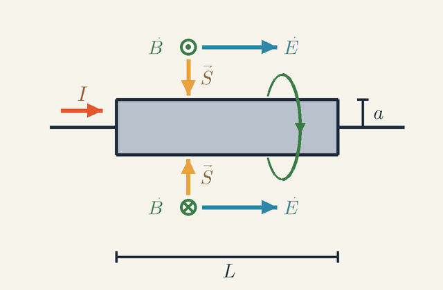
Two fields are involved. The surface charges produce an electric field in the space round the circuit, the current produces a magnetic field circling the wires, and together they carry an energy flux, in watts per square metre, S=μ0E×B where μ0 is the magnetic constant. This flux runs from the battery through the space between the wires into the rheostat and the bulb.
Figure 4. A cylindrical resistor of length L and radius a carrying a current I. Just outside its side E runs along the rod and B circles it, so S=E×B/μ0 points into the rod from every side. Not to scale.Legend
L
Length of the resistor.
m
a
Radius of the resistor.
m
I
Current through the resistor.
A
E
Electric field just outside the side: along the rod, in the direction of the current.
V/m
B
Magnetic field of the current: it circles the rod, out of the page above it and into the page below.
T
S
Energy flux E×B/μ0: it points into the rod, down at the top and up at the bottom.
W/m2
Figure 4 checks this on one resistor of the loop: a cylinder of length L and radius a carrying the current I to the right. Look at the two fields just outside its side, then at their cross product.
The electric field: the potential falls steadily by V along the length L. The component of the field along a surface is the same just inside and just outside it, so outside the side E also runs along the rod, in the direction of the current, with size V/L. In the figure it is the pair of arrows labelled E, pointing right above and below the rod.
The magnetic field: the current's field circles the rod by the right-hand rule (thumb along I, fingers curling the way B goes), as the ring round the rod shows. At the surface its size is μ0I/(2πa). Above the rod B comes out of the page; below it, B goes into the page.
The flux: S is perpendicular to both fields. Above the rod E points right and B out of the page, so S points down, into the rod. Below the rod B is reversed, so S points up, again into the rod. The same holds all the way round: S points straight in from every side. Since E and B are at right angles, its size is S=μ0EB=LV⋅2πaI=2πaLVI Multiplied by the side area 2πaL, the inflow is exactly VI, the power the resistor dissipates. Each resistor takes in its power through its surface, from the space around it.
Inside the battery the picture reverses. There E points against the current, from + to −, while the chemical force drives the charge the other way, so S points outward and the battery sends energy into the surrounding space. The wires guide the energy along the circuit; they do not carry it inside the copper.
Limits of validity
Every model has a range where it works, and it is worth knowing where this one ends.
The lumped picture assumes that a change at one point of the circuit is felt everywhere at once. That holds when the circuit is much smaller than the wavelength λ=c/f of its signals, where c is the speed of light and f the frequency. For 50 Hz mains λ is 6000 km, so any household circuit qualifies; at 1 GHz it is only 30 cm, and a circuit board radiates and must be treated with transmission lines. Even at DC the model skips the transient that follows closing a switch, but with a bench loop's inductance of about a microhenry the animation's current would settle within a few tenths of a microsecond.
Ohm's law is a property of materials, not a law of nature, though an excellent one for metals at a fixed temperature. A filament's resistance rises about tenfold from cold to white-hot, so a lamp draws a surge at switch-on; diodes and gas discharges are not ohmic at all, and a superconductor has R=0 exactly below its critical temperature. Nor is a battery ideal: its internal resistance r grows as it ages or gets cold.
At the smallest scale R=ρL/A fails altogether. A wire only a few atoms wide conducts in steps of the conductance quantum, 2e2/h≈7.75×10−5S, where conductance is the reciprocal of resistance, measured in siemens; that is about 12.9 kΩ per conducting channel, set by quantum mechanics rather than by the material or the length.
Where this leads
A capacitor in the loop adds a charge that changes, I=dQ/dt, and the loop rule becomes a differential equation: the exponential charging of Capacitors, with time constant RC. An inductor adds an induced emf, the subject of Electromagnetic Induction, where ∮E⋅dl=−dΦ/dt; a resistor, an inductor and a capacitor together obey the damped-oscillator equation of Damping and Resonance. Electric Power and Energy at Home turns P=VI into kilowatt-hours and fuses. Electric Current and Resistance, the lesson before this one, explains where ρ comes from; Semiconductors, Diodes and LEDs covers the most useful non-ohmic elements; and Electromagnetic Waves shows S carrying energy through empty space.
Key formulas
Ohm's law
V=IR
The voltage across a component equals the current through it times its resistance. For an ohmic component R is a constant, so the current is proportional to the voltage and the V–I graph is a straight line through the origin with slope R. Read the other way, R=V/I defines the resistance even when it is not constant.
Symbols
V
voltage across the component
V
I
current through the component
A
R
resistance of the component
Ω
When it holds: Holds for metals and ordinary resistors at a steady temperature. A filament's resistance rises as it heats up, a diode conducts one way only, and a superconductor has R=0.
Example: The animation's bulb at 0.80 A: VB=0.80⋅10=8.0V.
Resistors in series
Rseries=R1+R2
Resistors in series carry the same current, so their voltages IR1 and IR2 add up to I(R1+R2): the chain behaves like one resistor whose resistance is the sum. Each resistor takes a share of the total voltage in proportion to its resistance. A longer chain simply adds more terms.
Symbols
Rseries
equivalent resistance of the chain
Ω
R1
resistance of the first resistor
Ω
R2
resistance of the second resistor
Ω
When it holds: Only for components on one path, with nothing branching off between them.
Example: The rheostat at 5 Ω and the 10 Ω bulb make 15 Ω, so 12 V drives 12/15=0.80A.
Resistors in parallel
Rparallel1=R11+R21
Resistors in parallel have the same voltage across them, and their currents V/R1 and V/R2 add up. Each branch gives the current another path, so the reciprocals, the conductances, add, and the combination is smaller than either resistor. For two resistors the rule gives R1R2/(R1+R2).
Symbols
Rparallel
equivalent resistance of the parallel group
Ω
R1
resistance of the first branch
Ω
R2
resistance of the second branch
Ω
When it holds: For components connected across the same two points. With N equal resistors R in parallel the result is R/N.
Example: Two 2.4 Ω headlamps in parallel: 2.4⋅2.4/(2.4+2.4)=1.2Ω.
Electrical power
P=VI=I2R=RV2
Each coulomb that falls through a voltage V gives up V joules, and I coulombs pass every second, so the power is VI. Ohm's law turns this into I2R, convenient in series where I is shared, and V2/R, convenient in parallel where V is shared. In a resistor all of it becomes heat (and, in a lamp, partly light).
Symbols
P
power converted in the component
W
V
voltage across the component
V
I
current through the component
A
R
resistance of the component
Ω
When it holds:P=VI holds for any component, including motors and batteries being charged; the forms I2R and V2/R only for a resistance that obeys V=IR.
Example: The bulb at the start: PB=0.802⋅10=6.4W; at 0.40 A it drops to 1.6 W.
Kirchhoff's junction rule
∑I=0at a junction
In a steady circuit no charge builds up at a junction, so whatever flows in must flow out. Count the currents flowing in as positive and those flowing out as negative: their sum is zero. This is conservation of charge.
Symbols
I
each current meeting at the junction, positive if it flows in and negative if it flows out
A
When it holds: Exact for steady currents. For changing currents it holds as long as the junction itself stores no charge, which fails at very high frequencies.
Example: Two 5.0 A headlamps and a 10 A heater: the battery lead carries 5.0+5.0+10=20A.
Kirchhoff's loop rule
∑ε=∑IRaround a loop
Going once round a closed loop brings a charge back to its starting potential, so the energy given by the sources equals the energy lost in the resistors. An emf counts as positive if you pass through it from − to +, and an IR term as positive if you go through the resistor in the direction of its current. This is conservation of energy, based on ∮E⋅dl=0 for a static field.
Symbols
ε
emf of each source in the loop
V
I
current in each resistor of the loop
A
R
resistance of each resistor, internal resistances included
Ω
When it holds: Needs no changing magnetic flux through the loop; with an inductor or a changing external field, the induced emf −dΦ/dt must be added.
Example: The animation's loop at the start: 12=5I+10I, so I=0.80A.
Resistance of a wire
R=AρL
A wire twice as long is like two equal resistors in series, so R doubles; a wire with twice the cross-section is like two in parallel, so R halves. What remains is a property of the material alone, the resistivity ρ, which spans more than 20 orders of magnitude from metals to insulators.
Symbols
R
resistance of the wire
Ω
ρ
resistivity of the material
Ωm
L
length of the wire
m
A
cross-sectional area
m2
When it holds: For a uniform wire with the current spread evenly over its cross-section, at a given temperature. It fails for films thinner than the electrons' mean free path and at high frequency, where the current crowds near the surface.
Example: A metre of 1 mm² copper wire: R=1.7×10−8⋅1.0/10−6=0.017Ω.
Glossary
Electric circuit
A closed path of conductors round which charge can circulate, driven by a source such as a battery. Opening it anywhere stops the current everywhere at once.
Direct current (DC)
A current that flows in one direction with a steady value, as from a battery. Mains electricity is alternating current instead: it reverses direction periodically, 50 or 60 cycles per second.
Conventional current
The direction in which positive charge would flow: out of the + terminal, round the external circuit and into the − terminal. In a metal the electrons drift the other way, which carries the same current.
Potential difference (voltage)
The energy gained or lost per unit charge between two points, V=W/q, in volts: 1V=1J/C. It always refers to two points; the voltage drop across a component is the energy each coulomb gives up there.
Ohm's law
The proportionality V=IR, with R constant, between the voltage across a component and the current through it. Metals at a steady temperature obey it and are called ohmic; a filament lamp, which heats up as the current grows, and a diode do not.
Rheostat
A variable resistor: a sliding contact selects how much of a resistance wire is in the circuit. In the animation the purple slider sets it between 5 Ω and 20 Ω.
Series connection
Components one after another on a single path. They carry the same current, their voltages add up, and so do their resistances: Rseries=R1+R2.
Parallel connection
Components connected across the same two points. They have the same voltage, their currents add up, and the combination has less resistance than any one branch.
Kirchhoff's junction rule
The currents flowing into a junction add up to the currents flowing out, ∑I=0. It is conservation of charge in a steady circuit.
Kirchhoff's loop rule
Around any closed loop, the emfs add up to the sum of the IR drops. It is conservation of energy: a charge that goes once round comes back to its starting potential.
Short circuit
A path of almost no resistance across a source. The current is then limited only by the internal resistance and can be dangerously large: 12/0.02=600A for a car battery with 0.02 Ω inside.
Thévenin equivalent
A single emf in series with a single resistance that behaves, at two chosen terminals, exactly like a whole linear network. A real battery, an emf with its internal resistance, is the simplest example.
Quantities
I
Current
A
The charge passing a point per second, I=Q/t. In a series loop it has the same value everywhere: 0.40 to 0.80 A in the animation.
ε
Electromotive force (emf)
V
The energy a source gives each coulomb that passes through it, 12 V for the animation's battery. It equals the terminal voltage only when no current flows or the source has no internal resistance.
φ
Electric potential
V
The energy per coulomb at a point, measured from a chosen zero such as the − terminal. The voltage across a component is the difference of the potentials at its two ends.
V
Voltage
V
The energy each coulomb gains or loses between two points, V=W/q. Across the animation's bulb it varies between 4.0 and 8.0 V.
R
Resistance
Ω
The voltage needed per ampere, R=V/I. The animation's rheostat varies between 5 and 20 Ω, and its bulb has 10 Ω.
r
Internal resistance
Ω
The resistance inside a real source, which makes its terminal voltage ε−Ir fall as the current grows.
Rseries
Series resistance
Ω
The single resistance equivalent to resistors in series: the sum of their resistances.
Rparallel
Parallel resistance
Ω
The single resistance equivalent to resistors in parallel. It is smaller than the smallest of them. Its reciprocal is the sum of the branch conductances G=1/R, in siemens (1S=1A/V).
P
Power
W
The energy converted per second, P=VI. The animation's bulb converts between 1.6 and 6.4 W.
ρ
Resistivity
Ωm
A property of the material that sets the resistance of a wire, R=ρL/A for length L and cross-section A; 1.7×10⁻⁸Ωm for copper.
Quiz
Beginner A bulb is connected to a battery. What happens to the current if you add a second resistor in the same loop?
It increases
It decreases
It stays the same
It reverses direction
Show answer
Answer: B. It decreases
The extra resistor makes it harder for charge to flow around the loop, so with the same battery the current is smaller and the bulb dimmer.
Beginner Compared with the current flowing into a bulb, the current flowing out of it is:
Smaller, because the bulb uses some of it up
Zero
The same
Larger, because the bulb heats up
Show answer
Answer: C. The same
Charge is not used up: every charge that enters the bulb leaves it. The bulb takes energy from the charges, not the charges themselves.
Beginner What does the battery do in a circuit?
It fills empty wires with new charges
It creates electrons from chemicals
It makes the wires resist the current
It pushes the charges already in the wires and gives them energy
Show answer
Answer: D. It pushes the charges already in the wires and gives them energy
The wires are already full of mobile charges. The battery acts like a pump, providing the push (voltage) that keeps them moving and transfers energy.
Intermediate A 9 V battery is connected to a 30 Ω resistor. What is the current?
0.3 A
270 A
3.3 A
0.03 A
Show answer
Answer: A. 0.3 A
I = V/R = 9 / 30 = 0.3 A. Multiplying instead of dividing gives 270 A; dividing the wrong way round gives 3.3 A.
Intermediate Resistors of 6 Ω and 3 Ω are connected in parallel. What is their combined resistance?
9 Ω
4.5 Ω
2 Ω
0.5 Ω
Show answer
Answer: C. 2 Ω
1/R = 1/6 + 1/3 = 1/2, so R = 2 Ω, smaller than either resistor. 9 Ω is the series value; 0.5 is 1/R, not R.
Intermediate A 9 V battery drives a current through a 12 Ω rheostat and a 6 Ω bulb in series. What is the voltage across the bulb?
6 V
4.5 V
3 V
9 V
Show answer
Answer: C. 3 V
I = 9 / (12 + 6) = 0.5 A, so V_B = 0.5 × 6 = 3 V. The rheostat takes the other 6 V, and the two drops add up to 9 V. 4.5 V would be an equal split, which only happens when the resistances are equal.
Advanced A battery of emf 12 V and internal resistance r = 2 Ω drives a variable load resistor R. For which R is the power delivered to the load largest?
R = 0, because the current is then largest
R as large as possible, because the voltage across it is then largest
R = 4 Ω
R = 2 Ω
Show answer
Answer: D. R = 2 Ω
P = ε²·R/(R + r)², and dP/dR = ε²·(r − R)/(R + r)³ is zero at R = r = 2 Ω, giving 12²/(4·2) = 18 W. At R = 0 there is no voltage across the load, and for very large R almost no current flows, so the power tends to zero at both extremes.
Advanced Which principle does Kirchhoff's loop rule (the voltages around any closed loop sum to zero) express?
Conservation of charge
Conservation of energy, because the electrostatic field is conservative
Newton's third law
Conservation of momentum
Show answer
Answer: B. Conservation of energy, because the electrostatic field is conservative
Going round a loop brings a charge back to the same potential, so the energy gained in sources equals the energy lost in resistors. The junction rule is the one that expresses conservation of charge.
 Physics Tutor