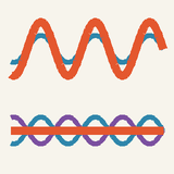
Light passing through two narrow slits a distance d apart makes bright fringes where dsinθ=mλ and dark ones in between: the classic experiment that shows light behaving as a wave.
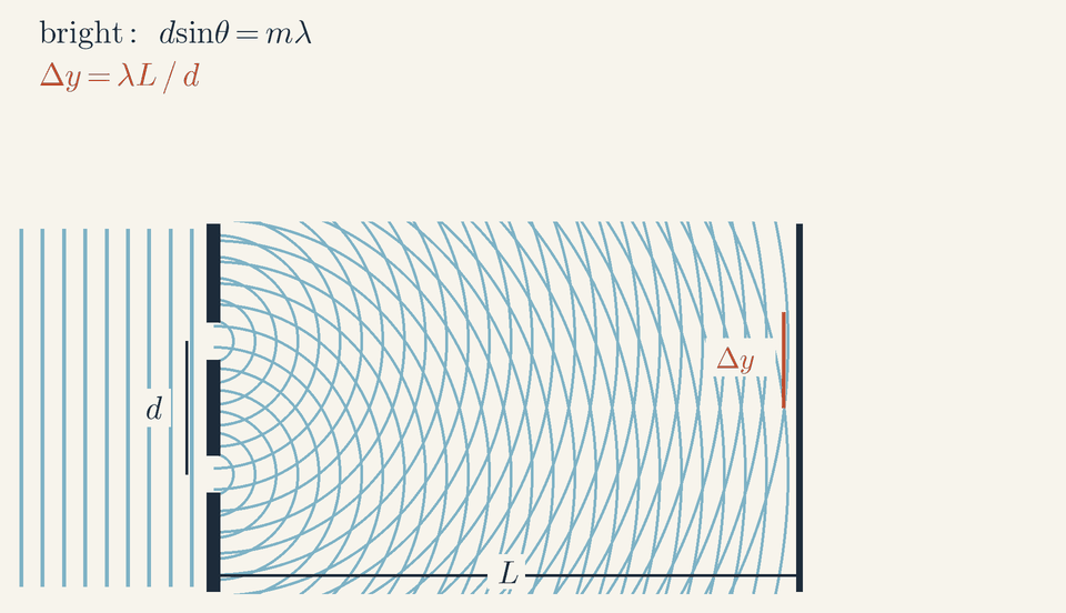
Plane light waves pass through two slits; the circular waves from each slit overlap and build up bright and dark interference fringes on the screen.
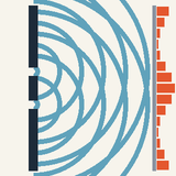
Squeezing through a very narrow gap, a wave spreads out on the other side: that is diffraction, and narrower gaps spread it more.
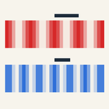
Light from two slits overlaps: crest on crest makes a bright stripe, crest on trough a dark one.
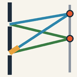
The middle stripe is bright because both paths are equal; at the next bright stripe one path is a whole wave longer.
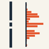
Light plus light can make darkness; cover one slit and the stripes vanish into one smooth patch.
Step 1, light can turn corners, a little. We line things up by sighting along them because light normally goes straight. But squeeze light through a very narrow gap and it fans out on the other side. This spreading is called diffraction. Sound does the same through an open door, which is why you hear people around a corner; for light the gap must be tiny, because light waves are so short. The narrower the gap, the wider the spread. Tiny bullets would fly straight through; only waves spread like this.
Step 2, two gaps. Now give the light two narrow slits close together. Each sends out its own circular ripples, and the two sets overlap. Where a crest from one slit meets a crest from the other, they team up and the screen is bright. Where a crest meets a trough, they cancel and the screen stays dark. This adding up of waves is interference.
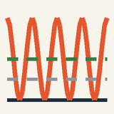
In the animation, straight waves arrive from the left, spread out from both slits, and the screen fills with bright and dark stripes; the orange bars show how bright each spot is.
Step 3, why stripes. The middle stripe is bright because it is equally far from both slits, so the waves arrive in step. Move up a little and one path gets longer: half a wave longer gives darkness, a whole wave longer gives the next bright stripe.
Light added to light can make darkness. Thomas Young found this with these slits around 1801, and it convinced physicists that light is a wave. Cover one slit and the stripes vanish, leaving one smooth patch.
Check yourself: at a spot on the screen one path is exactly two wavelengths longer than the other. Bright or dark? Answer: bright, because the crests arrive together again.
Intermediate
Key ideas
Bright where the path difference Δr=mλ (m=0,±1,±2…); dark where Δr=(m+21)λ.
Far from the slits Δr=dsinθ, so bright fringes satisfy dsinθ=mλ.
Fringe spacing Δy=λL/d: 600 nm, 0.25 mm and 1.0 m give 2.4 mm; red light gives wider fringes than blue.
Dark fringes are not shadows: energy moves from dark to bright fringes (peaks 4×, average 2× one slit), and the light must be coherent.
Diffraction: waves spread through openings
Light seems to travel in straight lines, which is why shadows have sharp edges. Yet every wave spreads out after passing through an opening: this is diffraction. By Huygens' principle each point of a wavefront acts as a source of new wavelets, and the wave further on is their sum. A wide opening rebuilds a straight beam; a narrow one acts almost as a single source, and the wave fans out in circles.
For a wavelength λ and an opening of width a, the spread is about λ/a radians. Sound, with wavelengths near 1 m, pours through a doorway into the whole room; green light, with λ≈500nm, spreads from a hole 1 mm wide by only half a millimetre per metre. To show light diffracting, a slit must be a fraction of a millimetre wide.
Two slits lit by one wave
In the animation straight crests reach two narrow slits a distance d apart, with a screen a distance L behind them. The same crest arrives at both slits at once, so they send out wavelets in step: they are coherent sources. A point on the screen at distances r1 and r2 from the slits is bright or dark depending on the path difference Δr=r2−r1.
Where one path is longer by a whole number of wavelengths, crest arrives with crest; where it is longer by an odd number of half wavelengths, crest arrives with trough:
Δr=mλ(bright)
Δr=(m+21)λ(dark)
Here m=0,±1,±2,… is the order of the fringe. The central fringe, m=0, is bright because the axis is equally far from both slits; the orders are negative below the axis and positive above it, as on the animation's readout.
From path difference to angle
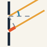
Seen from a distant screen (L≫d), the two paths to a point are practically parallel, at an angle θ from the central axis. A perpendicular dropped from the upper slit onto the lower path cuts off a small right triangle whose hypotenuse is d and whose side opposite the angle θ is the extra path, Δr=dsinθ
The conditions for bright and dark fringes therefore become conditions on the angle: dsinθ=mλ(bright) dsinθ=(m+21)λ(dark) Since sinθ≤1, at most d/λ orders fit on each side.
Near the axis the small-angle approximation sinθ≈tanθ=y/L holds, where y is the height on the screen, so the bright fringe of order m sits at ym=mλL/d and the fringes are equally spaced: Δy=dλL Red light, slits closer together and a more distant screen all give wider fringes.
Worked example: the pattern in the animation
The drawing is not to scale. In pixels it has λ=8, d=50 and L=220, so the slits are only 6.25 wavelengths apart, where real ones are hundreds. The small-angle formula gives Δy=dλL=508⋅220=35.2px
The first bright fringe has sinθ1=λ/d=0.16, so θ1=9.2∘. Its exact position, where r2−r1=λ, is 35.9 px above the centre, the length of the Δy mark beside the screen: at 9° the small-angle formula is only 2 % short.
Follow the probe dot up the screen, trailing the green path r1 from the upper slit and the purple path r2 from the lower one. Its readout runs from −1.76λ at the bottom through 0 on the central fringe, 0.50 on the first dark fringe, 1.00 on the first bright one and 1.50 on the second dark one, to 1.76 at the top. So the screen holds three bright fringes (m=0,±1) and four dark ones; the second order, at 18.7°, lies just beyond the edge at 16.5°.
The orange bars show the side fringes at only about three quarters of the central height: the width of each slit, treated at the expert level, dims them.
Worked example: measuring the wavelength of light
Light with λ=600nm falls on slits d=0.25mm apart, and the screen is L=1.0m away. How far apart are the fringes? With every length in metres, Δy=0.25×10−3600×10−9⋅1.0=2.4×10⁻³m=2.4mm The first fringe lies at θ1=λ/d=2.4×10−3rad, about 0.14°, where the small-angle approximation is excellent. Fringes this fine are one reason the effect went unnoticed for so long.
Turned around, λ=dΔy/L measures wavelengths. With the same slits and screen, ten spacings of a laser pointer's fringes span 26 mm (measuring many spacings at once divides the error), so Δy=2.6mm and λ=LdΔy=1.0(0.25×10−3)⋅(2.6×10−3)=6.5×10⁻⁷m=650nm
White light holds all wavelengths at once. The central fringe is white, but violet (400 nm) gives fringes 1.6 mm apart and red (700 nm) 2.8 mm apart, so each first-order fringe is a small spectrum, violet inside and red outside; after two or three orders the colours overlap into a whitish glow.
Reading the fringes on the screen
The stripes and the orange bars show the intensity I, the power arriving on each square metre of the screen. For two narrow, equal slits it follows a smooth cos2 curve, bright bands and dark gaps of equal width, with each dark fringe halfway between two bright ones: in the animation the first dark fringe is 17.8 px from the centre and the first bright one 35.9 px.
Amplitudes add, and intensity goes as the square of the amplitude: at a bright fringe the amplitude doubles and the intensity is 22=4 times one slit's, while at a dark fringe it is zero. Averaged over many fringes it is exactly twice one slit's, because the light missing from the dark fringes has gone into the bright ones. Cover one slit and the fringes vanish into a broad, smooth patch.
Common mistakes
Dark fringes are not shadows of the wall between the slits: both slits light the first dark fringe, and covering either one makes that spot a quarter as bright as the central peak.
Moving the slits apart does not spread the fringes; it squeezes them. The spacing goes as 1/d, so halving d from 0.25 mm to 0.125 mm doubles Δy from 2.4 mm to 4.8 mm.
The formula Δy=λL/d holds only at small angles: for slits two wavelengths apart the first order is at 30°, where y=Ltan30∘=0.58L, not 0.5L.
Two separate lamps, or even two lasers, make no visible fringes: their phases wander far faster than the eye can follow, so only the sum of their intensities remains. Both slits must be lit by the same wave.
Where you meet it
Gratings with hundreds of lines per millimetre measure wavelengths in most spectrometers, and the rainbow on a CD comes from its tracks, 1.6 µm apart. Diffraction also limits sharpness: light passing through a telescope or the pupil of an eye, of diameter D, spreads by about λ/D, as The Eye, Cameras and Telescopes explains.
X-rays, with wavelengths near 0.1 nm, diffract from the rows of atoms in a crystal and reveal where the atoms sit. Electrons and even whole molecules build up the same fringes one at a time, the starting point of Wave–Particle Duality. Next, Polarization of Light turns to another property of light waves: the direction in which they vibrate.
Advanced
Key ideas
Fields add, not intensities: phasors with φ=kdsinθ sum to 2E0cos(φ/2), so I=I0cos2(φ/2).
Slit width a multiplies the fringes by (sinβ/β)2, β=πasinθ/λ; an order vanishes on an envelope zero (m=3 if d=3a).
N slits: the maxima stay at dsinθ=mλ but become N times narrower and N2 times higher: a diffraction grating.
Electrons sent one at a time build the same fringes: amplitudes add, P=∣ϕ1+ϕ2∣2; finding the slit destroys the pattern.
Adding the two fields
Two-slit fringes come from adding the waves themselves, not their brightnesses, so the first job is to add the two fields correctly. Let the slits be a distance d apart, and look at a distant point in the direction θ, measured from straight ahead, at distances r1 and r2 from the two slits. Each slit delivers a field of the same amplitude E0 and angular frequency ω: E0cos(ωt−kr1) from the first and E0cos(ωt−kr2) from the second, where k=2π/λ is the wavenumber. The term ωt is common to both, so only the phase difference matters: φ=k(r2−r1)=kdsinθ The last step uses the far-field path difference r2−r1=dsinθ; the next section checks how accurate it is.
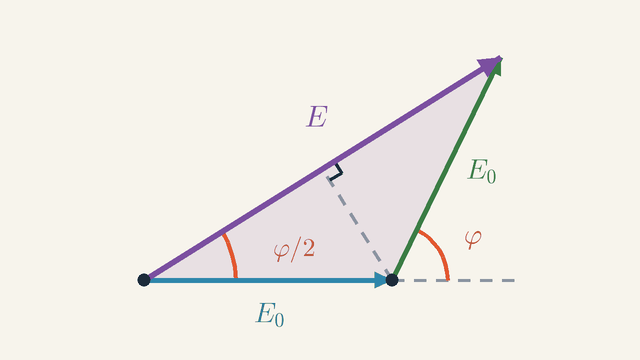
Figure 1. The fields of the two slits as phasors of length E0, the second turned by φ. Notice the isosceles triangle: its dashed altitude halves the resultant, so E=2E0cos(φ/2).Legend
E0
Amplitude of the field of one slit; both slits give the same.
V/m
φ
Phase difference of the two fields, φ=kdsinθ: the turn from the dashed extension of the first arrow to the second.
rad
φ/2
Half the phase difference: the angle between the resultant and the first phasor.
rad
E
Resultant (total field): the sum of the two phasors, closing the triangle.
V/m
Figure 1 adds the two fields as phasors. A phasor is an arrow whose length is the amplitude of an oscillation and whose angle is its phase; adding two oscillations of the same frequency is then the same as adding two arrows head to tail. The blue arrow is the field of the first slit, of length E0. The green arrow starts at its head and is the field of the second slit: the same length E0, but turned by φ away from the dashed extension of the blue arrow. The purple arrow E joins the start of the blue arrow to the tip of the green one, so it is the total field.
Now look at the shape. Two equal sides make an isosceles triangle, so its two base angles are equal, and together they equal the outside angle φ at the joint: each is φ/2. The dashed altitude from the joint meets E at a right angle and cuts the triangle into two equal right triangles, each with hypotenuse E0 and angle φ/2 at the tail of the blue arrow. Half of the resultant is therefore E0cos(φ/2), and the whole is E=2E0∣cos(φ/2)∣ The modulus keeps E positive when φ passes π and the cosine turns negative. Two checks: at φ=0 the arrows lie in one line and E=2E0; at φ=π they point in opposite directions and cancel.
A detector cannot follow the rapid oscillation of the field. It measures the intensity, which is proportional to the time average of the field squared, so I∝E2. Squaring E and writing φ/2=πdsinθ/λ gives I=I0cos2(λπdsinθ)
Here I0 is the intensity at the centre, where the two fields arrive in step. The amplitude there is doubled, so I0 is four times the intensity I1 of one slit alone. In Interference and Superposition I0 meant one source; here it means the central peak. No energy is created: the mean of cos2 over many fringes is 21, so the average intensity is I0/2=2I1, exactly what the two slits deliver together. Interference only moves light out of the dark fringes into the bright ones.
How accurate is the path difference?
The result above used r2−r1=dsinθ, which treats the two rays to the point as parallel. That is exact only infinitely far away, so it is worth knowing the error at a real screen.
Measure the distance R and the angle θ from the midpoint of the slits. The law of cosines gives each exact distance, r2=R2+d2/4±Rdsinθ, with the plus sign for the farther slit. Expand each square root in powers of d/R. Both distances contain the same second-order term d2cos2θ/(8R), which cancels in the difference; the first surviving correction is of third order: Δr=dsinθ(1−8R2d2cos2θ) So the relative error is at most (d/R)2/8: it shrinks with the square of d/R.
In the animation d/R≈0.22 at the first bright fringe, so the correction is only 0.6 %. On the screen, the exact curve r2−r1=λ (a hyperbola) meets it at 35.9 px, the far-field formula with y=Ltanθ gives 35.7 px, and the small-angle formula y=λL/d gives 35.2 px.
One slit of finite width
So far each slit was a point that sends the same amplitude E0 in every direction. A real slit has a width a, and every part of it acts as a source, so its brightness depends on direction. Adding those parts gives the slow envelope under the fringes.
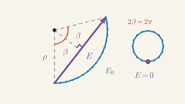
Figure 2. One slit of width a as a chain of tiny strip phasors, bent into an arc of length E0 that turns through 2β. The resultant is the chord, E=E0sinβ/β; at 2β=2π the arc closes into a circle and E=0.Legend
E0
Length of the arc: the amplitude straight ahead, where all strips are in phase.
V/m
E
Resultant of the strips: the chord from the start of the arc to its end.
V/m
ρ
Radius of the arc (dashed), in field units.
V/m
β
Half the angle the arc subtends at its centre; 2β=kasinθ is the phase difference between the edges of the slit.
rad
Figure 2 adds up the parts of one slit with phasors. Cut the slit into many narrow strips of equal width; each strip sends a tiny phasor, shown by the dots along the blue curve. In the direction θ each strip's path is longer than its neighbour's by the same small amount, so each phasor is turned from the one before by the same small angle. A chain of equal arrows, each turned by the same angle, bends evenly: it follows an arc of a circle, here of radius ρ (the dashed radii).
How far does the arc turn? The two edges of the slit differ in path by asinθ, so the first and last phasors differ in phase by kasinθ. The direction along an arc turns by the same angle as the arc subtends at the centre, so that central angle is kasinθ. Call it 2β; Figure 2 draws it as two halves β on either side of the dashed bisector. With k=2π/λ, β=λπasinθ
Now compare the arc with the chord. Straight ahead, at θ=0, all strips are in phase, the chain is a straight line, and its length is the full amplitude E0. In any other direction the tiny phasors are just as long, so the arc still has length E0, and since arc length is radius times angle, E0=2ρβ. The resultant is the purple chord E from the start of the arc to its end. The dashed bisector cuts it into two halves of ρsinβ, so E=2ρsinβ. Dividing the two removes ρ: E=E0βsinβ
The chord is always shorter than the arc, and it vanishes when the arc closes. At 2β=2π the chain curls into the full circle on the right of Figure 2, its end returns to its start (the purple dot), and E=0. This happens when the edges differ in path by one wavelength: asinθ=λ(first envelope zero)
A pairing argument gives the same zero without phasors. Split the slit into an upper and a lower half. Each strip in the upper half has a partner a/2 lower, whose path is then longer by λ/2, so the two cancel, and so does every pair.
In a double slit each slit sends the amplitude E0sinβ/β in the direction θ, the same for both. Putting this in place of E0 in the result of Figure 1 makes the two-slit pattern a product of fast fringes and a slow envelope: I=I0cos2(λπdsinθ)(βsinβ)2
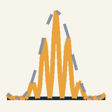
This is the graph in the animation's expert layer, whose formula writes sinθ as y/L. There a=14px=1.75λ and d=6.25λ. The first side peaks of the gold curve reach 0.77 of the central height, where they touch the dashed envelope; the envelope has fallen to 0.37 at the edges of the screen, and its first zero, at 34.8°, lies far off the screen.
A bright fringe that falls exactly on a zero of the envelope is missing. With d=3a the third order sits at sinθ=3λ/d=λ/a, the first envelope zero, and vanishes. In general, whenever d/a is a whole number n, the orders n, 2n, … are missing.
The pattern as a Fourier transform
The phasor sums of Figures 1 and 2 are two cases of one rule: the far-field amplitude is the Fourier transform of the aperture. This rule explains at once why the two factors multiply and why small features give wide patterns.
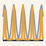
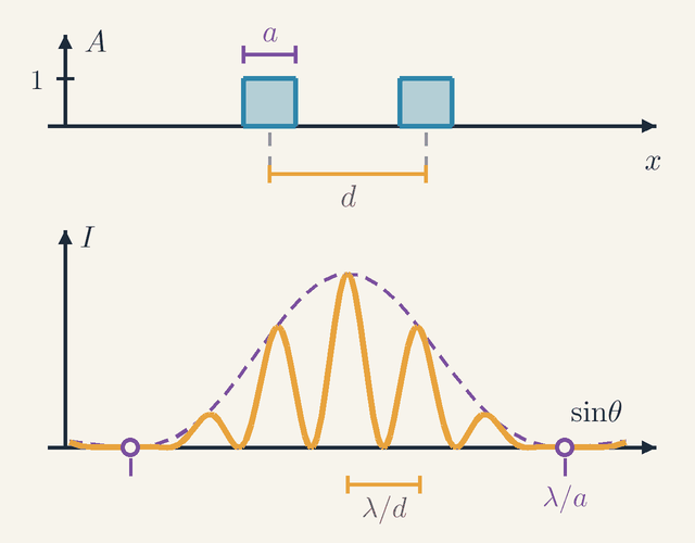
Figure 3. Top: the transmission A of two slits of width a, centres d=3a apart. Bottom: the far-field intensity I against sinθ. Same colours, inverse sizes: d sets the fringe period λ/d, a the envelope zeros at ±λ/a, where the third fringe is missing.Legend
A
Transmission of the aperture: 1 inside a slit, 0 on the wall.
x
Position across the aperture, along the line joining the slits.
m
a
Width of each slit.
m
d
Distance between the centres of the two slits.
m
I
Intensity of the pattern in the direction θ: gold fringes under the dashed envelope.
W/m2
sinθ
Sine of the angle θ of the outgoing light, measured from straight ahead; the horizontal axis of the pattern.
λ/d
Fringe period: the spacing of neighbouring bright fringes in sinθ.
λ/a
Value of sinθ at the first zeros of the envelope, marked by rings where a fringe is missing.
Figure 3 puts an aperture above its far-field pattern. The top graph is the transmission A against the position x across the aperture: A=1 inside each slit and A=0 on the wall between them. The slits have width a (purple bar) and centres a distance d apart (gold bar). The bottom graph is the intensity I against sinθ: gold fringes under a dashed purple envelope. Match the colours. The gold spacing d sets the gold fringe period λ/d, and the purple width a sets the purple envelope, whose first zeros are at sinθ=±λ/a. Here d=3a, so the third fringe on each side lands on an envelope zero and is missing, at the rings.
Here is the rule. Far from the aperture, a strip of width dx at the position x has a path that differs by xsinθ from that of the strip at x=0, by the same geometry as for the two slits, so its phase differs by kxsinθ. Write each contribution as a complex exponential, weight it by the transmission A(x) and add over all strips: E(θ)∝∫A(x)e−iqxdx,q=ksinθ This integral is the Fourier transform of A(x), with q in the role of the spatial frequency.
It reproduces both earlier results. Two very narrow slits at x=±d/2 give e−iqd/2+eiqd/2=2cos(qd/2), and since qd/2=πdsinθ/λ, its square is the cos2 fringes. One slit of width a, from −a/2 to a/2, gives asin(qa/2)/(qa/2)=asinβ/β, because qa/2=β: the envelope.
Two wide slits are one wide slit copied to two places. In the language of transforms, the aperture is the single slit convolved with the pair of narrow slits, and the transform of a convolution is the product of the transforms. That is why the fringe factor and the envelope multiply.
The transform also shows the reciprocity behind all diffraction: a feature of size s in the aperture makes structure on the angular scale λ/s. In Figure 3 the large spacing d makes the fine fringes and the small width a the broad envelope. A lens forms the far-field pattern in its focal plane, at a finite distance, and the X-ray patterns that revealed the structures of crystals are the squared magnitudes of the transform of the crystal's electron density.
Many slits: the diffraction grating
Adding more slits at the same spacing keeps the bright fringes in the same places but makes them far sharper and brighter. That sharpness is what makes a grating a precise tool for measuring wavelengths.
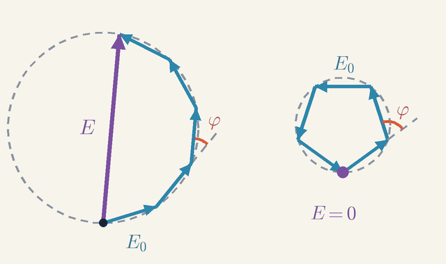
Figure 4. Left: five slits give five phasors of length E0, each turned by φ from the last; their corners lie on a circle and the closing side E is the resultant. Right: at φ=2π/5 the polygon closes and E=0, the first zero beside a principal maximum.Legend
E0
Amplitude of the field of one slit: the length of each phasor.
V/m
φ
Phase step between neighbouring slits, φ=kdsinθ: the turn from one phasor to the next.
rad
E
Resultant of all the phasors: the closing side of the polygon.
V/m
The left half of Figure 4 adds the fields of N=5 equal slits with spacing d. Each blue arrow has length E0 and is turned by the same angle φ=kdsinθ from the one before; the angle is marked at one joint. Equal arrows with equal turns trace part of a regular polygon, so all the corners lie on one circle (dashed). The purple resultant E is the closing side of the polygon, from the first tail to the last head.
The circle gives the length of E. A chord that subtends an angle α at the centre of a circle of radius ρ has length 2ρsin(α/2). Each side turns by φ, so, as in Figure 2, it subtends φ at the centre and E0=2ρsin(φ/2). The closing side spans all N sides and subtends Nφ, so E=2ρ∣sin(Nφ/2)∣. Dividing removes ρ, and squaring gives I=I1(sin(φ/2)sin(Nφ/2))2 where I1 is the intensity from one slit. For N=2 the ratio is sinφ/sin(φ/2)=2cos(φ/2), so this is 4I1cos2(φ/2) again, the two-slit result.
Whenever φ is a whole multiple of 2π, all the arrows point the same way and line up: E=NE0, and the intensity reaches N2I1. These principal maxima stay where dsinθ=mλ, just as for two slits.
The same chain of arrows also sets how narrow each maximum is. Moving away from a maximum, the chain curls up and first closes at φ=2π/N: that is the right half of Figure 4, a closed pentagon with E=0 (the purple dot). So the half-width of each maximum, from its peak to its first zero, is 1/N of the spacing 2π between maxima, N/2 times narrower than with two slits. Between neighbouring maxima lie N−1 zeros and N−2 weak secondary peaks. The light is concentrated, not created: the mean intensity is still NI1.
A grating with 500 lines per millimetre has a spacing of 2.0 µm. For 600 nm light λ/d=0.3, so sinθ=mλ/d is 0.3, 0.6 and 0.9 in the first three orders: they leave at 17.5°, 36.9° and 64.2°. A fourth order would need sinθ=1.2 and does not exist.
Two nearby wavelengths count as separated when the maximum of one falls on the first zero of the other. Take the angle of the order-m maximum of λ+Δλ, where dsinθ=m(λ+Δλ). There the phase step for λ is 2πm+2πmΔλ/λ, and it must exceed 2πm by the first-zero step 2π/N. Setting mΔλ/λ=1/N gives the resolving power λ/Δλ=mN The yellow sodium lines, 589.0 and 589.6 nm, need about 1000 lines in the first order. 2 cm of this grating holds 10,000 lines and, in the first order, separates lines 0.06 nm apart at 600 nm.
Worked problem: slit sizes from a pattern
Laser light of 600 nm passes a double slit, and a screen 1.0 m away shows fringes 2.4 mm apart. The fringes fade towards the sides, and the fifth on each side, at ±12 mm, is missing, leaving nine in the central band. Find the slit separation d, the slit width a, and the brightness of each fringe.
The fringe spacing gives the separation. Neighbouring bright fringes differ in path by one wavelength, so for small angles Δy=λL/d, and d=λL/Δy=(600×10−9⋅1.0)/(2.4×10−3)=0.25mm
The gap gives the width. The missing fringe sits on the envelope's first zero, asinθ=λ, which for small angles is at y=λL/a=12mm, so a=(600×10−9⋅1.0)/(12×10−3)=0.050mm Thus d=5a, which is why the fifth order is the one missing. A check on the far field: a2/λ=4.2mm, far below 1.0 m, so the far-field formulas apply.
At the fringe of order m, sinθ=mλ/d, so β=πasinθ/λ=πma/d=πm/5. Every bright fringe has cos2=1, so its brightness is set by the envelope alone: (sinβ/β)2 gives 1, 0.88, 0.57, 0.25 and 0.05 of the centre for m=0 to 4, then 0 for m=5. Beyond the gap the fringes return in a side band whose brightest fringe stays below 5 % of the centre.
The animation has d/a=50/14=3.57, not a whole number, so no order is lost completely. Its first orders reach 0.77, the second 0.31 and the third only 0.033, just inside the envelope's zero at m=3.57; a wide enough screen would show seven fringes in the central band. Slits widened to a=d/3≈16.7px would remove the third order exactly.
One quantum at a time
The same pattern survives when the light is so dim that it arrives one photon at a time, and it appears for electrons too. Here the rule for adding fields becomes the central rule of quantum mechanics.
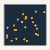
Dim the light until photons arrive one at a time: the screen records single flashes at random points, yet after many thousands of flashes they pile up into the same cos2 fringes. Electrons do the same, with the de Broglie wavelength λ=h/p, where p is the momentum and h Planck's constant. Accelerated through 100 V, an electron has λ=0.123nm, so slits 1 µm apart would give fringes 0.12 mm apart on a screen 1 m away.
The rule is the one for fields, applied to probability amplitudes. Each way of reaching a point has a complex amplitude, ϕ1 through one slit and ϕ2 through the other, and the probability of arriving there is the squared magnitude of their sum: P=∣ϕ1+ϕ2∣2=∣ϕ1∣2+∣ϕ2∣2+2∣ϕ1∣∣ϕ2∣cos(kΔr) The first two terms are the single-slit patterns. The last term is the interference, with k=p/ℏ and ℏ=h/(2π); without it the slits would simply add their single-slit patterns, with no fringes.
Recording which slit each particle passes removes the cross term, and the fringes go with it. The reason is the kick the measurement gives. Light that can tell the slits apart must have a wavelength below about d, so each of its photons carries a momentum of at least about h/d. Scattering one turns the particle's path by up to about (h/d)/p=λ/d, which is one fringe spacing in angle, and kicks of random size smear the fringes away, as Wave–Particle Duality explains.
Limits of validity
The scalar theory used here treats light as a single wave amplitude, ignoring the direction of its electric field, and treats the slits as holes in a perfectly black screen. That works for slits several wavelengths wide. A slit narrower than one wavelength has no envelope zero (asinθ=λ needs a≥λ), spreads light almost evenly behind it, and transmits differently for fields along it and across it, a polarization effect the scalar picture leaves out.
Fringes also need coherence: the waves must keep a steady phase relation. A spread of wavelengths Δλ limits the coherence length, the path difference over which the phase stays steady, to about λ2/Δλ. For white light that is about 1 µm, only two or so wavelengths, so only the first two or so orders show colours, while a laser, coherent over centimetres to metres, gives fringes far out.
A source of angular size α blurs the pattern too. Each point of the source makes its own copy of the pattern, shifted in angle by its own direction, and the copies wash out once α approaches the fringe spacing λ/d. For the 0.25 mm slits of the worked problem that is 2.4 mrad, but the Sun spans 9.3 mrad, so direct sunlight makes fringes only through slits closer than about 0.06 mm: hence the pinhole or single slit in front of classic set-ups. Partial coherence lowers the visibility V=(Imax−Imin)/(Imax+Imin) below 1.
Finally, the envelope formula assumes the far field, L≫a2/λ; nearer, in the Fresnel regime, the pattern changes shape with distance. The two-slit fringe positions need only d≪L, as the section on the path difference showed. That is why the animation's fringes obey dsinθ=mλ although d2/λ=312px exceeds L=220px.
Where this leads
Many slits make the grating at the heart of most spectrometers, and the line spectra they record lead to Atomic Models: the Bohr Atom. A round aperture of diameter D spreads light into a spot of angular radius 1.22λ/D, the resolution limit of The Eye, Cameras and Telescopes. The fields that add here are those of Electromagnetic Waves, and their direction of oscillation is the subject of Polarization of Light.
The amplitude rule P=∣ϕ1+ϕ2∣2 is the core of quantum mechanics: Wave–Particle Duality builds it up from single electrons, and Schrödinger's Equation and Tunnelling turns it into a wave equation for matter.
Key formulas
Path difference far from the slits
Δr=dsinθ
At a distant point the paths from the two slits are nearly parallel, and one is longer than the other by a side of a small right triangle whose hypotenuse is the slit separation: dsinθ. The sign follows the side of the axis, positive above it and negative below. It turns a question about two distances into one about a single angle.
Symbols
Δr
path difference, r2−r1
m
d
slit separation, centre to centre
m
θ
angle of the point from the central axis
rad
When it holds: Needs L≫d, with the angle measured from the midpoint of the slits. Near the axis the relative error is about d2/(8L2), only 0.6 % even in the animation's close-up geometry.
Example: Slits 0.25 mm apart and a point at θ=2.4×10⁻³rad: Δr=(0.25×10−3)⋅(2.4×10−3)=6.0×10⁻⁷m, one wavelength of 600 nm light.
Bright fringes
dsinθ=mλ(bright)
When the path difference is a whole number of wavelengths, the waves from the two slits arrive crest with crest and reinforce each other. The order m counts those wavelengths: m=0 is the central fringe, and the orders run outward on both sides with opposite signs. Since ∣sinθ∣≤1, no order can exceed d/λ.
Symbols
d
slit separation
m
θ
angle of the fringe from the central axis
rad
m
order of the fringe, 0,±1,±2,…
λ
wavelength
m
When it holds: Coherent light of one wavelength falling straight onto the slits, and a distant screen (L≫d). Light arriving at an angle shifts the whole pattern sideways.
Example: In the animation d=6.25λ, so the first order is at sinθ=1/6.25=0.16, or 9.2°, and at most six orders exist on each side.
Dark fringes
dsinθ=(m+21)λ(dark)
When the path difference is an odd number of half wavelengths, crest meets trough and the two waves cancel. With equal slits the cancellation is complete and the intensity drops to zero; the light missing there appears in the bright fringes. Dark fringes lie halfway between bright ones.
Symbols
d
slit separation
m
θ
angle of the fringe from the central axis
rad
m
whole number, 0,±1,±2,…
λ
wavelength
m
When it holds: Complete darkness needs equal amplitudes from the two slits and fully coherent light; otherwise the minima are only dimmer. The same far-field condition applies as for bright fringes.
Example: A path difference of 1.5 wavelengths (m=1) gives a dark fringe; in the animation it lies 54.7 px above the centre, where the readout shows 1.50.
Fringe spacing
Δy=dλL
For small angles sinθ≈tanθ=y/L, so the bright fringe of order m lies at ym=mλL/d and neighbours are a constant λL/d apart. The spacing grows with the wavelength and the screen distance and shrinks as the slits move apart. Measured on a screen, it gives the wavelength: λ=dΔy/L.
Symbols
Δy
distance between neighbouring bright fringes on the screen
m
λ
wavelength
m
L
distance from the slits to the screen
m
d
slit separation
m
When it holds: Small angles only: at 10° from the axis it is about 1.5 % short. At larger angles use dsinθ=mλ and y=Ltanθ; the fringes then spread out.
Example: Light of 600 nm, slits 0.25 mm apart, screen 1.0 m away: Δy=(600×10−9⋅1.0)/(0.25×10−3)=2.4mm.
Two-slit intensity pattern
I=I0cos2(λπdsinθ)
Each slit sends a wave of the same amplitude, their phase difference is φ=2πdsinθ/λ, and two equal phasors add to 2E0cos(φ/2). Squaring gives this cos2 pattern, with I0 the central intensity, four times one slit's. Averaged over the fringes it is I0/2, twice one slit's: energy is moved, not lost.
Symbols
I
intensity in the direction θ
W/m2
I0
intensity at the centre of the pattern
W/m2
d
slit separation
m
θ
angle from the central axis
rad
λ
wavelength
m
When it holds: Very narrow, equal slits and coherent light. For slits of width a, multiply by the single-slit envelope (sinβ/β)2 with β=πasinθ/λ, which dims the outer fringes.
Example: Halfway between a bright and a dark fringe, where Δr=λ/4: I=I0cos2(π/4)=I0/2.
First zero of the single-slit envelope
asinθ=λ(first envelope zero)
Divide one slit into an upper and a lower half. When its edges differ in path by one wavelength, every strip of the upper half has a partner a/2 lower whose path is longer by half a wavelength, and the pairs cancel. In phasor terms, the arc of small phasors closes into a full circle. This zero sets the width of the envelope that shapes the fringes.
Symbols
a
width of each slit
m
θ
angle from the central axis
rad
λ
wavelength
m
When it holds: Far field of the slit, L≫a2/λ. Further zeros lie at asinθ=2λ,3λ,…, and a slit narrower than λ has none. A bright fringe that lands on a zero is missing: with d=3a, the third order.
Example: Slits 0.050 mm wide lit with 600 nm light: sinθ=600×10−9/(0.050×10−3)=0.012, which is 12 mm from the centre of a screen 1.0 m away.
Glossary
Diffraction
The spreading of a wave after it passes through an opening or around an edge. It is strong when the opening is comparable to the wavelength, with a spread of about λ/a radians, so light shows it clearly only through slits a fraction of a millimetre wide.
Huygens' principle
Every point of a wavefront acts as a source of secondary wavelets, and the wave further on is their sum. A narrow slit therefore behaves like a single source of circular waves.
Young's double-slit experiment
Light from one source passes through two narrow, closely spaced slits and makes equally spaced bright and dark fringes on a screen. First performed in the early 1800s, it showed that light added to light can give darkness, as only waves can.
Interference fringes
The alternating bright and dark bands where coherent waves overlap. From one bright fringe to the next the path difference changes by one wavelength; on a distant screen they are λL/d apart.
Fringe order
The whole number m that labels a bright fringe: the number of wavelengths in its path difference. The central fringe is m=0, and at most d/λ orders fit on each side.
Coherent light
Light whose waves at the two slits keep a fixed phase relation, obtained by lighting both slits with one wavefront from a laser, a pinhole or a narrow slit. The fringes of two separate lamps shift too fast to see, and only their intensities add.
Small-angle approximation
For small angles sinθ≈tanθ≈θ in radians, which makes the fringes equally spaced, ym=mλL/d. At 10° the error is under 2 %.
Single-slit envelope
The slowly varying curve (sinβ/β)2, with β=πasinθ/λ, that diffraction by each slit of width a imposes on the fringes. The fringe positions come from d, their brightness from a.
Missing order
A bright fringe that falls exactly on a zero of the single-slit envelope and so does not appear. If d is a whole number n of slit widths, the orders n, 2n, … are missing: d=3a removes the third.
Far field (Fraunhofer diffraction)
The region far from an aperture, L≫a2/λ, or the focal plane of a lens, where the rays to one point are parallel and the pattern depends only on the angle. There the amplitude is the Fourier transform of the aperture.
Diffraction grating
A plate with many equally spaced slits or grooves. Its bright lines lie at the double-slit angles dsinθ=mλ, but with N slits their width shrinks as 1/N and their peaks reach N2 times one slit's intensity, so different wavelengths separate cleanly.
Probability amplitude
A complex number for each way a particle can reach a point; the probability is the squared magnitude of their sum. For two slits P=∣ϕ1+ϕ2∣2, which contains the interference term; if the slit used is recorded, the probabilities add instead.
Quantities
λ
Wavelength
m
The distance from one crest to the next, 400 to 700 nm for visible light. Every length in the pattern is measured against it.
d
Slit separation
m
The distance between the centres of the two slits, usually a fraction of a millimetre. The fringe spacing is inversely proportional to it.
a
Slit width
m
The width of each slit. It sets the single-slit envelope, whose first zero lies at asinθ=λ.
L
Slit-to-screen distance
m
How far the screen stands from the slits; the whole pattern grows in proportion to it.
θ
Angle from the central axis
rad
The direction of a point on the screen, seen from the midpoint of the slits; tanθ=y/L for a point at height y.
Δr
Path difference
m
How much farther the wave from one slit travels, r2−r1, which equals dsinθ far away. Whole wavelengths give bright fringes, odd half wavelengths dark ones. It is written Δ in Interference and Superposition.
m
Order
The whole number that labels a fringe, 0,±1,±2,…: the number of wavelengths in the path difference at a bright fringe.
Δy
Fringe spacing
m
The distance between neighbouring bright fringes on the screen, λL/d at small angles: 2.4 mm for 600 nm light, slits 0.25 mm apart and a screen 1.0 m away.
I
Intensity
W/m2
The power arriving on each square metre of the screen, proportional to the square of the total field amplitude. Its variation across the screen is the fringe pattern.
I0
Central intensity
W/m2
The intensity at the centre of the pattern, four times what one slit gives alone; the mean over many fringes is I0/2.
Quiz
Beginner In a double-slit experiment, what happens on the screen where a crest from one slit meets a trough from the other?
A dark stripe
A bright stripe
A stripe of a different colour
Nothing special happens
Show answer
Answer: A. A dark stripe
A crest and a trough cancel each other: this is destructive interference, which gives a dark stripe.
Beginner Why is the middle stripe on the screen bright?
It lies in the shadow of the wall
The light from both slits travels the same distance and arrives in step
Only one slit lights it
The light slows down there
Show answer
Answer: B. The light from both slits travels the same distance and arrives in step
At the centre the two paths are equally long, so crests arrive together and add up.
Beginner What happens to the striped pattern if you cover one of the two slits?
The stripes become sharper
The stripes move closer together
The stripes disappear and a single smooth patch remains
The screen goes completely dark
Show answer
Answer: C. The stripes disappear and a single smooth patch remains
The stripes come from light from the two slits adding and cancelling. With one slit covered, this two-slit interference is gone: the places that were dark now receive light, and the single narrow slit spreads its light into one broad, smooth patch.
Intermediate Light of wavelength 500 nm passes through slits 0.20 mm apart onto a screen 2.0 m away. What is the fringe spacing?
0.5 mm
2.5 mm
5.0 mm
50 mm
Show answer
Answer: C. 5.0 mm
Δy = λL/d = (500·10⁻⁹ × 2.0) / (0.20·10⁻³) = 5.0·10⁻³ m = 5.0 mm.
Intermediate At a point on the screen the path difference is 1.5 λ. What do you see there?
The central bright fringe
The first bright fringe
The second bright fringe
A dark fringe
Show answer
Answer: D. A dark fringe
A half-integer number of wavelengths (1.5 λ) means crest meets trough: destructive interference, a dark fringe.
Advanced With both slits open, how bright is the central fringe compared with the same spot when only one slit is open?
Twice as bright
Four times as bright
Equally bright
Half as bright
Show answer
Answer: B. Four times as bright
The two waves arrive in step, so the amplitude doubles, and intensity goes as amplitude squared: 2² = 4 times. Averaged over the whole pattern the intensity is only twice that of one slit: the energy missing from the dark fringes appears in the bright ones.
Advanced Two slits have separation d = 4a, where a is the width of each slit. Which interference order is missing?
m = 2
m = 3
m = 4
None are missing
Show answer
Answer: C. m = 4
Maxima occur at sin θ = mλ/d and the envelope's first zero at sin θ = λ/a = 4λ/d, so the m = 4 maximum falls on a zero and vanishes.
Advanced Electrons are sent through a double slit one at a time. What is observed?
Each electron makes a faint copy of the whole pattern
Two bright bands behind the slits only
Single dots that gradually build up the interference fringes
No pattern, because electrons are particles
Show answer
Answer: C. Single dots that gradually build up the interference fringes
Each electron is detected at one point, but the probability |ψ|² follows the fringe pattern, so many hits build it up.
 Physics Tutor