How the force F=BIL on a current in a magnetic field drives motors, how a coil spinning at ω generates an alternating EMF ε=NBAωsinωt, and how a transformer changes the voltage in the ratio of its turns, Ns/Np.
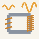
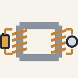
A coil spins between the poles of a magnet and generates an alternating voltage, which a transformer steps up to light a lamp.
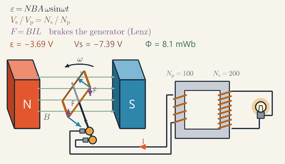
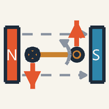
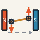
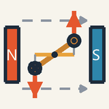
A coil carrying a current between a magnet's poles is pushed up on one side and down on the other, so it turns.
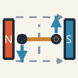
To keep a motor turning one way, the current in its coil is reversed every half turn by a split ring.
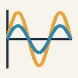
Turn the coil yourself and it becomes a generator: its current reverses every half turn, which is alternating current (AC).
A transformer's coils share an iron ring: more turns on the output coil give a higher voltage, but a smaller current.
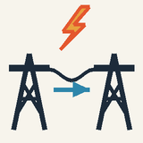
Power lines use very high voltage, so the current is small and far less energy is lost heating the cables.
Put a loop of wire between the poles of a magnet and send a current round it. One side of the loop is pushed up, the other side down, so the loop twists. Left alone, the loop swings round until it lines up with the magnet and stops. To keep it spinning, the current in the loop must be reversed every half turn; a split ring turning with the loop, rubbing on two fixed contacts, does exactly that. You now have an electric motor, the heart of a drill, a fan or an electric car.
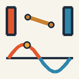
Run the machine backwards and it becomes a generator. In the animation a coil keeps spinning between the north and south poles of a magnet, as a turbine would turn it in a power station. Its sides sweep through the magnetism and push a current round the circuit. Watch the red arrow on the wire: it grows, shrinks and points the other way every half turn. This is alternating current (AC), the kind in your sockets, and the lamp flashes twice per turn.
The current then reaches a transformer: two coils on one iron ring. The changing current in the first coil makes changing magnetism in the iron, which drives a current in the second coil. More turns on the second coil give a higher voltage, but never more power: ten times the voltage means a tenth of the current. That is why electricity travels at very high voltage: a small current in the cables wastes far less energy as heat.
Check yourself: a transformer has 50 turns in and 500 turns out. With 12 V AC going in, what comes out? Answer: 120 V, with a tenth of the current.
Intermediate
Key ideas
A wire across a field feels F=BILsinθ; on a coil the two sides make a torque τ=NBIAsinθ that drives a motor.
A coil turning at ω gives ε=NBAωsinωt: largest when its plane lies along B, zero when it faces B.
Ideal transformer: Vs/Vp=Ns/Np and VpIp=VsIs, so raising the voltage lowers the current by the same factor.
Transformers need AC: a steady DC current makes no changing flux, so no voltage appears in the secondary.
In the animation ε0=NBAω≈6.3V; with Ns/Np=2 the lamp's voltage peaks at 12.6 V, in phase.
Force on a wire, torque on a coil
A magnetic field pushes sideways on moving charges, and so on a wire that carries a current. For a straight wire of length L carrying a current I through a uniform field B, the force is F=BILsinθ where θ is the angle between the wire and the field: the force is largest when the wire crosses the field at right angles and zero along the field lines. It is perpendicular to both, and Fleming's left-hand rule gives its direction: first finger along the field, second finger along the current, thumb along the force. So 1 T pushes with 1 N on each metre of wire carrying 1 A across it.
Bend the wire into a rectangular coil of N turns and area A on an axle between the magnet's poles. Its two long sides carry opposite currents and are pushed opposite ways, so the coil feels a torque τ=NBIAsinθ where θ is now the angle between the field and the normal to the coil. The torque is largest when the plane of the coil lies along the field and zero when the coil faces the field, where a coil left alone comes to rest. A DC motor keeps turning thanks to a commutator, a split ring on the axle touched by two brushes, which reverses the current every half turn, just as the torque is about to reverse.
The generator: a motor run backwards
Remove the battery and turn the coil at a steady angular velocity ω. Measuring the angle from the position where the coil faces the field, the flux through each turn is Φ=BAcosωt, and Faraday's law, ε=−NdΦ/dt, gives the EMF and its peak value:
ε=NBAωsinωt
ε0=NBAω
This alternating EMF has frequency f=ω/2π. It is largest when the plane of the coil lies along the field: the sides then cut straight across the field lines, and the flux, passing through zero, changes fastest. It is zero when the coil faces the field, where the flux is largest but momentarily constant. Slip rings carry the EMF out without twisting the wires; a commutator in their place would give pulsing DC. Meters quote the root-mean-square (rms) value, the peak divided by 2 for a sine wave: a 230 V supply peaks at about 325 V.
Transformers: two coils, one flux
A transformer has no moving parts: a primary coil of Np turns and a secondary of Ns turns share one closed iron core. An alternating current in the primary makes an alternating flux that the iron guides through the secondary. Each turn of either coil links the same changing flux and gets the same EMF, so the voltages are in the ratio of the turns, and without losses the power in equals the power out:
VpVs=NpNs
VpIp=VsIs
A step-up transformer (Ns>Np) raises the voltage and lowers the current by the same factor, so no energy is created. A steady direct current makes a steady flux, which induces nothing, so a transformer needs AC. Large transformers are over 99 % efficient.
Worked example: the machine in the animation
The coil has N=200 turns of area A=0.020m2 (20 cm by 10 cm) in a field B=0.50T, and it makes one turn every 2 s, so ω=2π/2=π≈3.14rad/s. Then Φmax=BA=0.50⋅0.020=0.010Wb ε0=NBAω=200⋅0.50⋅0.020⋅π≈6.28V
At t=0 the coil faces the field: the Φ readout shows 10.0 mWb and the ε readout zero. An eighth of a turn later, at t=0.25s, the flux is 10cos45∘≈7.1mWb and the EMF 6.28sin45∘≈4.44V. At t=0.5s the plane of the coil lies along the field, Φ passes through zero and ε peaks at 6.28 V. At t=1s the flux is −10.0 mWb and the EMF is zero again.
With Np=100 and Ns=200, the secondary gives Vs=2ε, peaking at 12.57 V (about 12.6 V) on the Vs readout, in step with ε. The lamp's power grows as Vs2, so it flashes at both peaks, positive and negative: twice per turn.
Reading the arrows: why the generator resists
The blue v arrows show the long sides moving round their circle: at t=0 they slide along the field B and cut nothing; at t=0.5s they cross it at right angles. Only the motion across the field drives the charges, hence the sinωt. The purple F arrows are the motor effect inside the generator: the field pushes on the induced current with F=BIL, always against the motion. That is Lenz's law; if the forces helped instead, the coil would speed itself up and make energy from nothing.
How hard must the coil be turned to keep the lamp lit? Treat the lamp as a 25 Ω resistor. At the peak it carries 12.57/25≈0.50A, so the ideal transformer needs twice that, about 1.0 A, in the coil. The torque is then τ=NBIA=200⋅0.50⋅1.0⋅0.020=2.0N⋅m, and turning against it at πrad/s takes τω≈6.3W, exactly the lamp's peak power, 12.57⋅0.50≈6.3W. Disconnect the lamp and the coil turns freely.
Worked example: high-voltage power lines
A wind farm sends 20 MW through lines with a total resistance of 4.0 Ω. They heat up at the rate I2R, and for a given power the current is I=P/V, so Ploss=I2R=(VP)2R
At the generators' own 11 kV the current would be 20×106/(11×103)≈1818A, and the loss 18182⋅4.0≈13.2MW: two thirds of the power would only heat the wires. A step-up transformer with a turns ratio of 1 : 12 raises the voltage to 132 kV. The current falls to 151.5 A and the loss to 151.52⋅4.0≈92kW, under half a percent: twelve times the voltage, 122=144 times less loss. Step-down transformers near homes then bring it back to 230 V.
Common mistakes
A transformer does not work on steady DC: a 12 V battery gives 0 V on the secondary after a brief kick at switch-on.
The EMF is not largest when the coil faces the magnets: there the flux, 10 mWb in the animation, is largest but momentarily constant, so ε=0. The EMF peaks at 6.28 V when Φ=0.
A step-up transformer does not create energy: the lamp gets twice the coil's voltage but half its current, 0.50 A against 1.0 A, so both sides carry 6.3 W.
The two angles called θ differ: in F=BILsinθ it lies between wire and field, in τ=NBIAsinθ between field and normal, so a coil lying along the field has the largest torque.
Where you meet it
Electric motors drive fans, lifts, pumps and electric cars, and use close to half of the world's electricity. An electric car's motor even works as a generator when it brakes. A two-pole power-station generator turning at 3000 rpm gives the 50 Hz of the European grid, and transformers sit at both ends of every power line and inside phone chargers. The 230 V met in Electric Power and Energy at Home is an rms value, and the changing fields behind every transformer lead on to Electromagnetic Waves.
Advanced
Key ideas
Motional EMF BLvsinωt on each side adds up to ε=NBAωsinωt, the same as −NdΦ/dt with Φ=BAcosωt.
Energy balance: the counter-torque needs power τω=εI; in a motor a back EMF εb∝ω gives I=(V−εb)/R.
With all the flux in the iron core, Vp=NpdΦ/dt and Vs=NsdΦ/dt; a load R looks like (Np/Ns)2R from the primary.
Line loss Ploss=P2R/V2: ten times the voltage gives one hundredth of the loss.
Real cores lose energy to hysteresis and eddy currents; laminating the core cuts the eddy currents, and large transformers exceed 99 %.
Two routes to the same EMF
A generator is a coil of N turns, turned at a steady angular speed ω in a uniform magnetic field B. Faraday's flux rule gives its EMF in one line, but it hides what actually pushes the charges round the circuit. So we first find the EMF from the magnetic force on the charges inside the moving wire, and then check that the flux rule gives the same answer. Let each turn be a rectangle with two long sides of length L, parallel to the axle, and two short ends of length w, the width of the coil, so that its area is A=Lw.
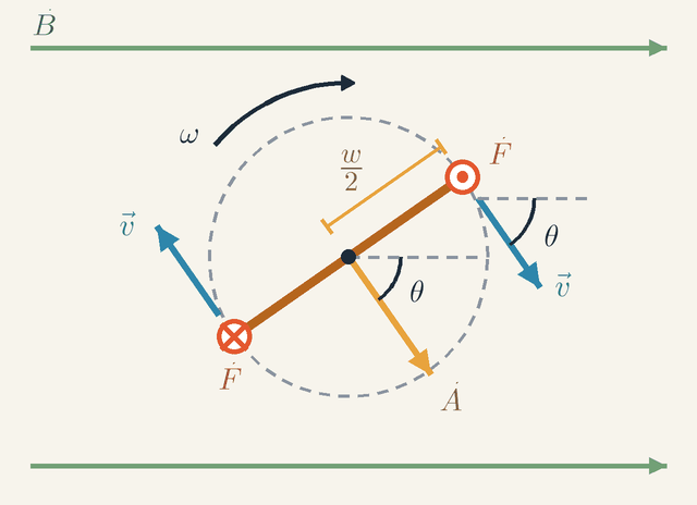
Figure 1. The coil seen end-on, its axle into the page, turning clockwise at ω in a field B. Notice that the velocity v of a long side and the area vector A both make the angle θ=ωt with B, and that the force F points along each side: out of the page on one, into it on the other.Legend
B
Magnetic field, uniform and horizontal in the plane of the figure.
T
ω
Angular speed of the coil, which turns clockwise here.
rad/s
2w
Radius of the circle on which each long side moves: half the width w of the coil.
m
v
Velocity of a long side, tangent to its circle, of size ωw/2.
m/s
θ
Angle between v and B, and also between A and B: θ=ωt.
rad
A
Area vector of the coil: size A=Lw, at right angles to the coil, so parallel to v of the upper side.
m2
F
Magnetic force qv×B on a positive charge q in a long side. It points along the wire: out of the page on the upper side (dot), into it on the lower side (cross).
N
Figure 1 looks along the axle, which points into the page. Each long side then appears as a small disc, and the coil itself as the line joining the two discs. The field B runs horizontally across the page, and the coil turns clockwise at ω.
Start with the motion of one long side. It lies a distance w/2 from the axle, so it moves on the dashed circle of radius w/2 with speed v=ωw/2. Its velocity v is tangent to that circle. Measure time from the moment when the sides move along the field lines, with v parallel to B. The velocity turns with the coil, so by time t it has turned through the angle θ=ωt, marked in the figure between v and the dashed horizontal line at the upper side.
Next, the force. A positive charge q carried along by the side feels the magnetic force F=qv×B. Both v and B lie in the plane of the page, so their cross product is perpendicular to the page, that is, along the wire. On the upper side it points out of the page (the dot); on the lower side, whose velocity is reversed, it points into the page (the cross). Because θ is the angle between v and B, the force has size qvBsinθ=qvBsinωt.
Now the work. The EMF is the work done on a unit charge carried once round the circuit. Along a long side the force per unit charge, vBsinωt, points along the wire over the whole length L, so it does the work BLvsinωt per unit charge. The short ends lie in the plane of the page; the force on their charges still points along the axle, straight across the wire, so it does no work along them.
Finally, go once round a turn. Along the upper side we travel out of the page, the same way as the force there. Along the lower side we come back into the page, and the force there also points into the page, so it again pushes the way we travel. The two sides therefore add rather than cancel, and each turn gives 2BLvsinωt. The N turns are connected in series, so their EMFs add too: ε=2NBL2ωwsinωt=NBAωsinωt where the last step uses A=Lw.
The flux route is shorter. The area vector A has size A and stands at right angles to the plane of the coil. In Figure 1 it is parallel to the velocity of the upper side, because that velocity is also at right angles to the coil. So A turns with v and makes the same angle θ=ωt with B. The flux through one turn is therefore Φ=BAcosωt, largest at t=0, when the coil faces the field. Faraday's law gives ε=−NdtdΦ=−NBAdtdcosωt=NBAωsinωt the same result.
Put in the animation's numbers. Its coil has L=0.20m along the axle and w=0.10m across, so A=0.020m2, with N=200 turns in B=0.50T, turning at ω=πrad/s (one turn every 2 s). Each long side moves at v=π⋅0.05≈0.157m/s and contributes at most BLv=0.50⋅0.20⋅0.157≈15.7mV. The 200 turns have 400 long sides, all in series, so the peak EMF is 400⋅15.7mV≈6.28V, the same as NBAω=200⋅0.50⋅0.020⋅π.
The two routes agree, but they describe different physics. In the generator the wire moves, and the magnetic force on its moving charges does the pushing; the flux rule is a compact summary of that force. In a transformer nothing moves, so there is no force qv×B at all. Instead, the changing flux creates an electric field that circulates round the core, ∮E⋅dl=−dtdΦ and this electric field drives the charges in the secondary coil. The fact that one rule covers two such different mechanisms hints that electric and magnetic fields are two aspects of a single field, which relativity makes precise.
Reading the graph: flux leads the EMF
The animation's graph shows the flux and the EMF together. Reading it well means seeing Faraday's law as a statement about slopes, which is the quickest way to sketch any induced EMF from its flux.
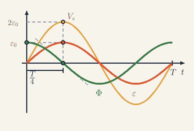
Figure 2. One period T of the generator. The EMF ε follows minus the slope of the flux Φ: zero at a flux crest, largest where Φ falls through zero (dashed tangent), a quarter period T/4 later. The secondary voltage Vs keeps the shape of ε and is twice as tall.Legend
Φ
Magnetic flux through one turn, BAcosωt, drawn scaled to the height of ε0.
Wb
ε
EMF of the coil, −NdΦ/dt.
V
ε0
Peak EMF of the coil, NBAω.
V
Vs
Voltage of the transformer's secondary coil; its peak is 2ε0 for Ns/Np=2.
V
t
Time.
s
T
Period: the time of one turn of the coil.
s
4T
A quarter period: the time by which the flux leads the EMF, a phase of 90∘.
s
Figure 2 redraws that graph over one period T, the time of one turn: here T=2π/ω=2s. The green curve is the flux Φ(t) through one turn, scaled to the height of the EMF so that the two are easy to compare. The red curve is the EMF ε(t). The gold curve, which we come to below, is the output Vs(t) of a transformer fed by the generator.
First compare where the curves peak. The flux Φ=BAcosωt has a crest at t=0, and the EMF has its first crest a quarter period later, at T/4=0.5s. The flux leads the EMF by a quarter cycle, a phase of 90∘. The pattern repeats every period, so the flux crests again at 2 s, 4 s and so on.
Next see why. Faraday's law, ε=−NdΦ/dt, says that the EMF is minus N times the slope of the green curve. At a crest or a trough of Φ the curve is flat for an instant, so ε=0 there, even though the flux itself is at its largest. Where Φ falls through zero, at T/4, it is at its steepest; the dashed tangent shows that slope, and there ε reaches its peak +ε0=+6.28V. Half a period later Φ rises through zero just as steeply, and ε=−6.28V.
The numbers confirm it. The flux through one turn has amplitude BA=0.50⋅0.020=10mWb, so the flux linkage NΦ has amplitude 200⋅10mWb=2.0Wb. A cosine of amplitude a and angular frequency ω has a steepest slope of aω, here 2.0⋅π≈6.28Wb/s. Since 1Wb/s=1V, that is the peak EMF ε0.
The gold curve Vs(t) has the same zeros and crests as ε(t) but is twice as tall, peaking at 2ε0. An ideal transformer copies the waveform, scales it by its turns ratio, here Ns/Np=2, and adds no phase shift; Figure 4 shows why.
Last, what single number to quote for such a voltage. A resistor R driven by ε0sinωt takes the power (ε02/R)sin2ωt. Over a cycle sin2ωt averages 21, because sin2 and cos2 have the same average and add up to 1. So the mean power is half the peak power, the same as a steady voltage ε0/2 would give. This is the root-mean-square (rms) value, here 6.28/2≈4.44V.
Energy balance: the generator pays in torque
A generator turns mechanical work into electrical energy, so something must resist the rotation; otherwise the coil would deliver power for nothing. That something is the magnetic force on the very current the coil delivers.
Let the coil deliver a current I in phase with its EMF, as it does into a resistor. In each turn, a long side carries I along a length L at right angles to B, so it feels a force BIL, directed at right angles to B in the plane of Figure 1. Only the part of this force along the side's velocity v turns the coil. Since v makes the angle ωt with B, that part is BILsinωt, and by Lenz's law it acts against v, at the lever arm w/2. Two sides per turn and N turns give the counter-torque τ=2N(BILsinωt)2w=NBIAsinωt To keep the coil turning at a steady ω, whoever drives it must supply this torque, so the mechanical power put in is τω=(NBIAsinωt)ω=(NBAωsinωt)I=εI exactly the electrical power delivered, at every instant.
Which force does the work? Not the magnetic one: it is always perpendicular to each charge's total velocity, the sum of the coil's motion and the charge's drift along the wire, so it does no work at all. It only redirects work. The part of the force due to the coil's motion pushes the charges along the wire and drives the current; the part due to their drift along the wire pushes sideways on the wire and resists the rotation. These two works are equal and opposite, so all the electrical energy comes from whoever turns the shaft.
The motor: back EMF and the torque line
Run the same machine as a motor and the coupling works the other way round. The supply drives a current, the force on that current turns the coil, and the turning coil, being a generator too, makes an EMF that opposes the supply. This back EMF is what sets a motor's current and speed, and it decides how much torque the motor can give at each speed.
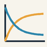
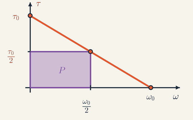
Figure 3. Torque against speed for a motor on a fixed supply voltage: a straight line from the stall torque τ0 at rest down to zero at the no-load speed ω0. The mechanical power P=τω is the area of the shaded rectangle, largest at half the no-load speed.Legend
ω
Speed of the motor shaft.
rad/s
τ
Torque the motor delivers; it falls linearly as ω rises.
N⋅m
τ0
Stall torque, kV/R: the torque with the shaft held, ω=0.
N⋅m
ω0
No-load speed, V/k: the back EMF equals the supply voltage, no current flows and the torque is zero.
rad/s
2ω0
Half the no-load speed, where the mechanical power is largest.
rad/s
2τ0
Half the stall torque: the torque at ω0/2.
N⋅m
P
Mechanical power τω, the area of the shaded rectangle; at ω0/2 it has its largest value, V2/(4R).
W
Figure 3 plots the torque τ that a motor delivers against the speed ω of its shaft, for a fixed supply voltage V applied through the resistance R of its winding.
To see why the graph is a straight line, model the motor. With many coils on the rotor and a commutator that switches each coil in at the right moment, the back EMF εb is nearly steady and proportional to the speed. Three equations then describe the motor: V=εb+IR,εb=kω,τ=kI The first is the circuit: the supply voltage is shared between the back EMF and the drop across the winding. The second and third contain the same constant k, and they must: the energy balance above, εbI=τω, holds only if the constant linking εb to ω equals the one linking τ to I.
The first equation gives the current, I=(V−kω)/R, and the third turns it into a torque: τ=Rk(V−kω) This is the falling line of the figure. At its left end the shaft is held still, ω=0, so there is no back EMF and only the winding limits the current, to V/R; the torque is then the stall torque τ0=kV/R. As the speed rises the back EMF grows, so the current falls and the torque with it. At the right end, the no-load speed ω0=V/k, the back EMF has risen to the supply voltage, no current is left, and the torque is zero.
The mechanical power is P=τω. On the graph that is the area of a rectangle with one corner at the origin and the opposite corner on the line, like the shaded one. Writing the line as τ=τ0(1−ω/ω0) gives P=τ0ω(1−ω0ω) which is zero at both ends of the line. It is a parabola in ω, symmetric about the midpoint of its two zeros, so it is largest at ω=ω0/2, where the torque is τ0/2. The peak power is therefore (τ0/2)(ω0/2)=V2/(4R).
How much of the input becomes work? The motor takes the electrical power VI and turns εbI of it into mechanical power, so its efficiency, ignoring friction, is εb/V=ω/ω0. At the speed of peak power εb=V/2: only half the power taken in becomes mechanical power, and the other half heats the winding. Near the no-load speed, where the rectangle is wide but low, the efficiency is high.
Take a 12 V motor with R=0.50Ω. At start-up ω=0, so there is no back EMF and I=12/0.50=24A. Running at 3000 rpm, that is ω=3000⋅2π/60≈314rad/s, its back EMF is εb=11V, and it draws only (12−11)/0.50=2.0A. Of the 24 W taken in, εbI=22W becomes mechanical work and I2R=2W heats the winding, an efficiency of 92 %.
The running point also gives the motor constant, k=εb/ω=11/314≈0.035V⋅s/rad, so the torque is τ=kI=0.035⋅2.0=0.070N⋅m; as a check, τω=0.070⋅314≈22W.
Now place this motor on Figure 3. Its stall torque is τ0=kV/R=0.035⋅12/0.50≈0.84N⋅m and its no-load speed is ω0=V/k≈343rad/s, near 3270 rpm. So 3000 rpm lies close to the right-hand end of the line, where the torque is small and the efficiency ω/ω0 is high. The torque falls linearly with speed from 0.84 N·m to zero, and the mechanical power peaks at half the no-load speed, about 1640 rpm, at V2/(4R)=72W. There the motor draws (12−6)/0.50=12A, or 144 W, so only 50 % of it becomes work.
Inside the transformer
A transformer changes the size of an alternating voltage with no moving parts, which is why power grids run on AC. All its behaviour follows from one fact: the iron core makes the same flux pass through every turn of both coils.
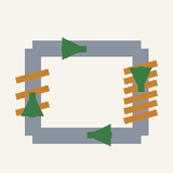
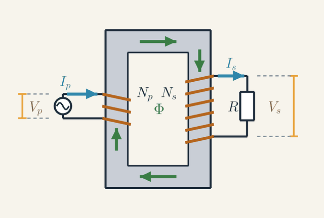
Figure 4. A transformer with a load. The source voltage Vp drives Ip through the Np primary turns and fixes the flux Φ in the core; the same Φ threads the Ns secondary turns, which drive Is through the load R at Vs. Notice that Is magnetises the core the opposite way to Ip.Legend
Vp
Voltage of the source across the primary coil.
V
Ip
Current in the primary coil.
A
Np
Number of turns of the primary coil.
Φ
Magnetic flux in the iron core, the same through every turn of both coils.
Wb
Ns
Number of turns of the secondary coil.
Is
Current in the secondary coil and the load.
A
Vs
Voltage across the secondary coil and the load.
V
R
Resistance of the load on the secondary.
Ω
Figure 4 shows a transformer with a load. The source applies the voltage Vp across the Np turns of the primary coil and drives the current Ip through them. The iron core carries the flux Φ round its closed loop, along the green arrows, so that the same Φ threads all Ns turns of the secondary coil. The secondary applies the voltage Vs to the load R and drives the current Is through it.
Since every turn of either coil links the same flux, every turn has the same EMF, dΦ/dt in size. Turns in series add, and with the resistance of the windings neglected each coil's terminal voltage equals its EMF, so in size Vp=NpdtdΦ,Vs=NsdtdΦ Dividing one by the other cancels dΦ/dt and leaves the turns ratio, Vs/Vp=Ns/Np. Both voltages follow the same dΦ/dt, so they also rise and fall together, with no phase shift, as Figure 2 showed.
Now read the first equation the other way round: the primary voltage fixes the flux, whatever the load. For a sinusoidal voltage of peak V0 the flux is a sinusoid too, of peak Φ0=V0/(Npω), because differentiating a sinusoid multiplies its amplitude by ω. A 230 V, 50 Hz primary of 1000 turns has V0≈325V and ω≈314rad/s, so Φ0≈1.04mWb. To keep the iron below about 1.2 T the core then needs a cross-section of Φ0/B≈8.6×10−4m2, some 8.6 cm². The area needed falls as 1/ω: at the 400 Hz used on aircraft an eighth of it would do, and chargers switching at tens of kilohertz use tiny ferrite cores.
Why does the primary current rise when a load is connected? The load current Is flows round the secondary turns and, on its own, would magnetise the core the opposite way to Ip; in Figure 4 the two currents circulate in opposite senses round the core. But the flux is fixed by Vp. So the primary must draw an extra current whose magnetising effect, measured by current times number of turns, cancels that of the secondary: NpIp=NsIs, apart from the small magnetising current that sets up the flux itself. Multiplying by the voltage ratio gives VpIp=VsIs: power in equals power out.
A transformer therefore also changes resistances. Seen from the primary, the load is Vp/Ip. Substituting Vp=(Np/Ns)Vs and Ip=(Ns/Np)Is gives IpVp=(NsNp)2R which is how a transformer matches a loudspeaker to an amplifier.
Two limiting cases remain: an open secondary and a direct current. With the secondary open, no current Is flows, and the secondary voltage is set by the primary current alone: in size Vs=MdIp/dt, where M is the mutual inductance of the two coils. On DC, dΦ/dt=0: nothing is induced in either coil, nothing crosses to the secondary, and only the copper's small resistance limits the primary current.
Worked problem: loading the generator
Connect a 25 Ω lamp, treated as a plain resistor, to the secondary of the animation's transformer (Np=100, Ns=200), whose primary is fed by the generator, and neglect the resistance of the coils. What current does the generator coil carry, how hard must it be turned, and what would change without the transformer?
First, the load as the coil sees it. From the primary, the lamp looks like (Np/Ns)2R=(100/200)2⋅25=6.25Ω. The coil drives its EMF, of peak 6.28 V, into this resistance, so the coil current is a sine wave in phase with the EMF, of peak 6.28/6.25≈1.01A. The secondary doubles the voltage and halves the current, so the lamp carries a peak of about 0.50 A at a peak of 12.57 V.
Next, the torque. The energy balance gave the counter-torque NBAIsinωt, where I is now the primary current Ip, itself proportional to sinωt. With NBA=200⋅0.50⋅0.020=2.0Wb, and 1Wb⋅A=1N⋅m, τ=NBAIpsinωt≈2.0sin2ωtN⋅m It peaks at 2.0 N·m when the plane of the coil lies along the field, where the EMF and the current are largest, and averages half of that, 1.0 N·m. As a check, the mean mechanical power, τˉω=1.005⋅π≈3.16W, equals the lamp's mean power, half its peak voltage times its peak current: 21⋅12.57⋅0.503≈3.16W.
Without the transformer the lamp would sit directly on the slip rings, a 25 Ω load instead of 6.25 Ω. It would take only ε02/(2R)=6.282/50≈0.79W, a quarter as much, and the coil would be four times easier to turn. The transformer creates no energy: by making the lamp look four times smaller in resistance, it lets the coil drive four times the current at the same EMF, and so deliver four times the power, all of it supplied by whoever turns the coil.
Notice, finally, that the torque varies as sin2ωt=21(1−cos2ωt): it throbs at twice the rotation frequency, which shakes a single-phase machine. Power stations avoid this with three sets of coils set 120∘ apart. The cos2ωt parts of their three torques are then a third of a cycle apart and cancel, since sin2θ+sin2(θ−120∘)+sin2(θ+120∘)=23 so a balanced three-phase generator gives a perfectly steady torque and power.
Limits of validity
The ideal transformer assumes three things: all the flux links both coils, the windings have no resistance, and the iron is magnetised for free and without loss. Real cores lose energy in two ways. Hysteresis costs a fixed amount of energy each time the iron's magnetisation is reversed, so its power loss grows roughly in proportion to the frequency. Eddy currents are currents induced in the iron itself; they grow as the square of both the frequency and the thickness of the iron sheets, which is why cores are built from insulated laminations about 0.3 mm thick. Large transformers reach 99.5 % efficiency, yet a 500 MVA unit then sheds 2.5 MW of heat, hence its oil tank and radiators.
Saturation sets a further limit. Silicon steel saturates near 1.5 to 2 T: beyond that, more current adds almost no flux. Since the flux is fixed by Φ0=V0/(Npω), a transformer run below its design frequency or above its design voltage is driven into saturation and draws huge currents.
The treatment is also quasi-static: the fields are taken to act everywhere at once. At 50 Hz the wavelength is c/f=6000km, so any machine is tiny by comparison, but a 1000 km line is a sixth of a wavelength and must be analysed as a transmission line. The flux rule also needs care when conducting material slides past a fixed contact, as in a spinning-disc generator, where it is unclear which loop the flux should be counted through. The force qv×B is then the reliable guide.
AC is not always best. A long cable has a large capacitance, which AC must keep charging and discharging. Beyond roughly 50 to 100 km of undersea cable, or several hundred kilometres of overhead line, high-voltage DC with electronic converters wins. Insulation, and corona discharge in the air round the conductors, cap the highest transmission voltages at around 1 MV.
Where this leads
The force on currents from Magnetic Force on Moving Charges and the flux rule from Electromagnetic Induction are all the physics a power grid needs. The induced electric field of every transformer, joined by its partner, a magnetic field made by a changing electric field, gives the self-sustaining waves of Electromagnetic Waves. In the frame moving with a side of the coil, the generator's magnetic push becomes an electric field: a first glimpse of Special Relativity. The rms values and power factor of AC supplies were treated in Electric Power and Energy at Home, and the rectifiers and inverters behind brushless motors and HVDC links come from Semiconductors, Diodes and LEDs.
Key formulas
Force on a current-carrying wire
F=BILsinθ
Each moving charge in the wire feels a sideways magnetic force; added up over all the charges in a length L, they give a force proportional to the current. Only the part of the wire that crosses the field counts, hence sinθ. The force is perpendicular to both the wire and the field (Fleming's left-hand rule), and reversing either the current or the field reverses it.
Symbols
F
force on the wire
N
B
magnetic field
T
I
current in the wire
A
L
length of wire inside the field
m
θ
angle between the wire and the field
rad
When it holds: For a straight wire in a uniform field. For a curved wire or a non-uniform field, add up the forces Idl×B on short pieces.
Example: A 15 cm wire carrying 4.0 A across a 0.25 T field: F=0.25⋅4.0⋅0.15=0.15N.
Torque on a coil
τ=NBIAsinθ
The two sides of each turn that cross the field feel equal and opposite forces BIL, a width w apart, which give a torque BILwsinθ=BIAsinθ per turn; N turns multiply it. The torque is largest when the plane of the coil lies along the field (θ=90∘) and zero when the coil faces the field, where the forces only stretch it.
Symbols
τ
torque on the coil
N⋅m
N
number of turns
B
magnetic field
T
I
current in the coil
A
A
area of the coil
m2
θ
angle between the field and the normal to the coil
rad
When it holds: For a flat coil of any shape in a uniform field. Real motors use curved pole pieces and many coils to keep the torque nearly constant; the formula then gives the torque on each coil.
Example: 50 turns of area 0.0020 m² carrying 2.0 A in 0.40 T: at most τ=50⋅0.40⋅2.0⋅0.0020=0.080N⋅m.
EMF of a rotating coil
ε=NBAωsinωt
A coil turning at a steady ω has a flux Φ=BAcosωt through each turn, and Faraday's law, ε=−NdΦ/dt, turns that into a sine wave. Equivalently, each side moving through the field has a motional EMF BLvsinωt. The time t=0 is the moment the coil faces the field, so the EMF starts from zero.
Symbols
ε
EMF at time t
V
N
number of turns
B
magnetic field
T
A
area of the coil
m2
ω
angular velocity of the coil
rad/s
t
time since the coil faced the field
s
When it holds: For a flat coil turning at constant speed about an axis perpendicular to a uniform field. A non-uniform field or a changing speed distorts the sine wave.
Example: The animation's coil: ε=6.28sinπt (in volts, with t in seconds), so at t=0.25s, ε≈4.44V.
Peak EMF of a generator
ε0=NBAω
The largest size of the alternating EMF, reached twice per turn (once with each sign) when the plane of the coil lies along the field and the flux, passing through zero, changes fastest. It is proportional to each of the four factors, so turning twice as fast doubles both the peak and the frequency.
Symbols
ε0
peak EMF
V
N
number of turns
B
magnetic field
T
A
area of the coil
m2
ω
angular velocity of the coil
rad/s
When it holds: Under the same conditions as the sine law. It is the peak value: a meter on AC shows the rms value, ε0/2.
Example: The animation's coil: ε0=200⋅0.50⋅0.020⋅π≈6.28V, with an rms value of 4.44 V.
Transformer voltage ratio
VpVs=NpNs
The iron core carries the same changing flux through every turn of both coils, so each turn has the same EMF, dΦ/dt. The voltage across a coil is that EMF times its number of turns, hence the ratio. More turns on the secondary step the voltage up; fewer step it down.
Symbols
Vs
voltage across the secondary coil
V
Vp
voltage across the primary coil
V
Ns
number of turns on the secondary
Np
number of turns on the primary
When it holds: For AC only, and for an ideal transformer: all the flux shared by both coils and negligible winding resistance. On steady DC the secondary voltage is zero.
Example: The animation: Vs=(200/100)⋅6.28≈12.6V at the peak.
Ideal transformer power balance
VpIp=VsIs
An ideal transformer neither stores nor wastes energy, so the power going in equals the power coming out at every instant. Whatever factor raises the voltage lowers the current by the same factor: the currents are in the inverse ratio of the turns, Is/Ip=Np/Ns.
Symbols
Vp
voltage across the primary coil
V
Ip
current in the primary coil
A
Vs
voltage across the secondary coil
V
Is
current in the secondary coil
A
When it holds: Real transformers lose some energy in the copper and in the core: large ones are more than 99 % efficient, small ones noticeably less.
Example: A 25 Ω lamp on the animation's secondary draws about 0.50 A at 12.6 V peak, so the coil supplies about 1.0 A at 6.28 V: about 6.3 W on both sides.
Power lost in a transmission line
Ploss=I2R=(VP)2R
The current in the line heats its resistance at the rate I2R. For a given power delivered the current is P/V, so the loss falls as the square of the voltage: ten times the voltage gives a hundredth of the loss. That is why grids step the voltage up with transformers before sending power far.
Symbols
Ploss
power turned into heat in the line
W
I
current in the line
A
R
total resistance of the line's conductors
Ω
P
power sent along the line
W
V
voltage at which the power is sent
V
When it holds: Treats the line as a single resistance carrying the whole current, with current and voltage in phase; three-phase lines and out-of-phase currents need corrections.
Example: 20 MW sent over 4.0 Ω: at 11 kV the loss would be 13.2 MW, at 132 kV only 92 kW.
Glossary
Motor effect
The sideways push of a magnetic field on a wire that carries a current, F=BILsinθ, at right angles to both the wire and the field. Fleming's left-hand rule gives its direction.
Electric motor
A machine in which the motor effect turns a coil, converting electrical energy into mechanical work. Small DC motors reverse their current with a commutator; many modern motors switch their coils electronically.
Commutator
A split ring on the axle, touched by two fixed brushes, that reverses the connections to the coil every half turn. In a motor it keeps the torque turning the coil the same way; on a generator it turns the alternating EMF into pulsing DC.
Back EMF
The EMF generated by a motor's own spinning coils, proportional to the speed and opposing the supply. It is why a motor draws a large current at start-up and a small one at full speed: I=(V−εb)/R.
Faraday's law of induction
A changing magnetic flux through a coil induces an EMF equal to the number of turns times the rate of change of the flux, ε=−NdΦ/dt. Only the change counts, not the size of the flux.
Lenz's law
An induced current flows in the direction that opposes the change producing it. In a generator it makes the forces on the induced current resist the rotation, so every joule delivered must be paid for with mechanical work.
Generator
A machine that turns mechanical work into electrical energy by moving a coil through a magnetic field, or a magnet past a coil. It is built like a motor and is a motor run the other way.
Slip rings and brushes
Two whole rings on a generator's axle, each touched by a sliding brush, that carry the alternating EMF out of the spinning coil without twisting the wires.
Alternating current (AC)
A current that reverses direction periodically, usually as a sine wave. A coil spinning in a field makes it naturally; power grids run at 50 Hz or 60 Hz.
Root-mean-square value
The steady value that would deliver the same average power to a resistor. For a sine wave it is the peak divided by 2: a 230 V supply peaks at about 325 V.
Transformer
Two coils on a shared iron core; an alternating current in one induces a voltage in the other in the ratio of their turns. A step-up transformer raises the voltage and lowers the current, a step-down one does the reverse, and neither works on steady DC.
Eddy currents
Swirling currents induced in a solid piece of metal by a changing flux. In a transformer core they waste energy as heat, so cores are built from thin, insulated sheets called laminations.
Quantities
B
Magnetic field
T
The strength of the magnetic field (the magnetic flux density): 1 T pushes with 1 N on each metre of wire carrying 1 A across it. The animation's magnet gives 0.50 T.
I
Current
A
The charge flowing past a point each second. In a generator it is driven by the EMF; in a motor it is set by the supply voltage minus the back EMF. On a transformer, Ip and Is are the primary and secondary currents.
F
Force on a wire
N
The sideways push of the field on a current-carrying wire, BILsinθ: the force that turns a motor and brakes a generator. Here L is the length of wire in the field (in m) and θ its angle to the field; on a coil the forces give a torque τ=NBIAsinθ (in N·m), with θ measured from the normal.
N
Number of turns
How many times the wire goes round a coil. Each turn adds the same EMF or the same torque, and a transformer's voltages are in the ratio of the turns of its two coils. There Np and Ns are the turns of the primary and the secondary, and Vp, Vs their voltages (in V).
Φ
Magnetic flux
Wb
The field times the area it crosses square on, BAcosθ for a flat coil; 1Wb=1T⋅m2. In the animation it swings between +10 and −10 mWb per turn. Here A is the area of the coil (in m²) and θ the angle between the field and its normal.
ω
Angular velocity
rad/s
How fast the coil turns, ω=2πf; it is also the angular frequency of the AC it makes. One turn every 2 s gives ω=πrad/s. In sinωt, t (in s) is the time since the coil faced the field.
ε
Electromotive force (EMF)
V
The energy given by induction to each coulomb pushed round the circuit. For a spinning coil it varies as sinωt.
ε0
Peak EMF
V
The largest value of the alternating EMF, NBAω: 6.28 V in the animation, with an rms value of ε0/2≈4.44V. Not to be confused with the vacuum permittivity ε0 of the electricity lessons.
P
Power transmitted
W
The rate at which a line delivers energy, P=VI, where V is the voltage at which it is sent (in V). For a given P, a higher voltage means a smaller current.
Ploss
Power lost in the line
W
The rate at which the line's conductors turn energy into heat, I2R, where R is the total resistance of the line (in Ω). For a given power it falls as the square of the transmission voltage.
Quiz
Beginner What does a generator do?
It turns electricity into motion
It turns motion into electricity
It stores electricity, like a battery
It makes a magnet stronger
Show answer
Answer: B. It turns motion into electricity
A generator uses motion (a turbine, an engine, a crank) to spin a coil in a magnetic field, which pushes a current round the circuit. A motor does the reverse.
Beginner Why does the current from a coil spinning between magnets keep changing direction?
The magnets keep swapping their north and south poles
The lamp pushes the current back
Each side of the coil moves one way across the field, then the other way, every turn
The wires heat up and stop the current
Show answer
Answer: C. Each side of the coil moves one way across the field, then the other way, every turn
Every half turn, each side of the coil reverses its direction of motion through the field, so the push on the charges reverses too. That is alternating current.
Beginner Why is electricity sent along long-distance cables at a very high voltage?
Much less energy is wasted heating the cables
Electricity travels faster at high voltage
Homes need such high voltages to work
Generators can only produce high voltages
Show answer
Answer: A. Much less energy is wasted heating the cables
For the same power, a higher voltage means a smaller current, and the heating of the cables depends on the current squared. Transformers near homes lower the voltage again.
Intermediate A 0.40 m wire carries a current of 5.0 A at right angles to a 0.30 T magnetic field. What force acts on it?
6.0 N
0.12 N
3.75 N
0.60 N
Show answer
Answer: D. 0.60 N
F = B·I·L = 0.30 × 5.0 × 0.40 = 0.60 N. Forgetting the current gives 0.12 N, and dividing by L instead of multiplying gives 3.75 N.
Intermediate A transformer has 200 turns on its primary and 50 turns on its secondary. With 240 V AC on the primary, what is the secondary voltage?
960 V
60 V
240 V
4.8 V
Show answer
Answer: B. 60 V
Vs = Vp·Ns/Np = 240 × 50 / 200 = 60 V: a step-down transformer. Turning the ratio upside down gives 960 V.
Intermediate A coil spins at a steady rate in a uniform magnetic field. At which position is the induced EMF largest?
When the coil's plane lies along the field, so its sides cut straight across the field lines
When the coil's plane faces the field, so the flux through it is largest
Halfway between those two positions
The EMF is the same at every position
Show answer
Answer: A. When the coil's plane lies along the field, so its sides cut straight across the field lines
ε = N·B·A·ω·sin ωt is largest when the flux Φ = B·A·cos ωt changes fastest, which happens when the flux itself passes through zero, with the coil's plane along the field. Where the flux is largest, it is momentarily not changing and ε = 0.
Advanced A DC motor draws a large current when it starts, but much less once it runs at full speed. Why?
The commutator disconnects the coil at high speed
Friction drops as the motor warms up
The spinning coil generates a back EMF that grows with speed and opposes the supply
The magnets weaken as the motor heats up
Show answer
Answer: C. The spinning coil generates a back EMF that grows with speed and opposes the supply
A turning coil is also a generator. Its back EMF ε_b ∝ ω opposes the supply, so I = (V − ε_b)/R falls as the motor speeds up; at start-up ε_b = 0 and only the coil's small resistance limits the current.
Advanced An ideal transformer with Np : Ns = 1 : 10 feeds a 500 Ω load on its secondary. What resistance does the source see at the primary?
50 Ω
50 000 Ω
5000 Ω
5 Ω
Show answer
Answer: D. 5 Ω
Vp = Vs·Np/Ns and Ip = Is·Ns/Np, so Vp/Ip = (Np/Ns)²·Vs/Is = (1/10)² × 500 Ω = 5 Ω. Forgetting the square gives 50 Ω; using Ns/Np instead gives 5000 Ω or 50 000 Ω.
 Physics Tutor