Push a magnet into a coil and a current flows with no battery; pull it out and the current flows the other way.
Only change counts: a magnet resting inside the coil, however strong, makes no current at all.
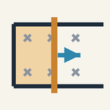
Moving a wire across a magnet's field works too: the charges carried along with it are pushed along the wire.
The induced current fights the change, so you must work to move the magnet: that work becomes the electrical energy.
Faster motion, a stronger magnet or more turns give a bigger current; generators and bike dynamos use this.
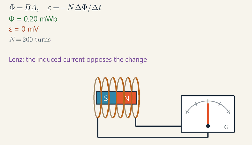
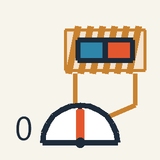
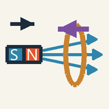
Connect a coil of wire to a sensitive current meter. There is no battery anywhere, so the needle rests at zero. Now push a bar magnet into the coil: the needle kicks to one side. Hold the magnet still inside, and the needle drops back to zero. Pull it out, and the needle kicks the other way.
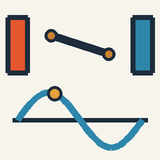
This is electromagnetic induction, discovered by Michael Faraday in 1831. The rule is short: a current flows only while the magnetism passing through the coil is changing. A huge magnet lying still does nothing; a small one moved quickly does something. The animation shows the three stages: magnet moving in, magnet resting, magnet moving out.
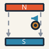
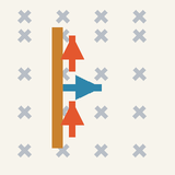
You have already met the reason. A magnet pushes sideways on moving charges. Move a wire across a magnet's field and the charges inside the wire are carried along with it, so they get pushed along the wire: that push is the induced current. It does not matter what moves, the magnet or the wire.
The induced current always fights the change that made it. As the magnet comes in, the coil turns into a little magnet that pushes it back; as it leaves, the coil tries to hold it. So you must do work to move the magnet, and that work is exactly where the electrical energy comes from.
Moving faster, using a stronger magnet or winding more turns all make a bigger current. Power-station generators, bicycle dynamos and wireless chargers all rely on this.
Check yourself: a magnet rests inside a coil that is joined to a meter. What does the meter show? Answer: zero, because nothing is changing.
Intermediate
Key ideas
Flux Φ=BAcosθ (1Wb=1T⋅m2) measures how much field threads a loop.
Faraday's law: ε=−NΔΦ/Δt. Only a changing flux induces an EMF, however large Φ is.
Changing B, the area A or the angle θ all change the flux and induce an EMF.
Lenz's law: the induced current opposes the change in flux, so moving the magnet takes work, which becomes electrical energy.
Magnetic flux: how much field threads a loop
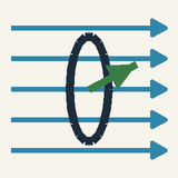
Most of the world's electricity comes from generators that turn magnets past coils, and every one of them relies on the same rule. Induction is driven not by a magnetic field as such but by a change in how much field passes through a circuit: the magnetic flux. For a flat loop of area A in a uniform field B, Φ=BAcosθ where θ is the angle between the field and the normal, the line perpendicular to the plane of the loop. A field straight through the loop gives θ=0 and Φ=BA; a field lying in the plane gives Φ=0, because no field line crosses the loop.
Flux is measured in webers, 1Wb=1T⋅m2, and it has a sign: reverse the field or turn the loop over and the flux changes sign. A coil of N turns, like the animation's 200, responds to the flux linkage NΦ, since each turn carries the same flux.
Faraday's law: only change counts
Faraday's law states that a changing flux induces an electromotive force (EMF) in a coil of N turns: ε=−ΔtNΔΦ The EMF, measured in volts, is the energy given to each coulomb that goes once round the circuit, and the formula gives its average over the interval Δt. Through a circuit of resistance R it drives a current I=ε/R.
The flux Φ=BAcosθ can change in three ways, and each of them induces an EMF:
Change the field B: move a magnet, or switch an electromagnet on or off.
Change the area A: stretch the loop, or slide a rod along rails.
Change the angle θ: rotate the coil, which is how a generator works.
The size of the flux itself does not matter. While the magnet rests inside the coil, from 2.6 s to 4.6 s, the Φ readout holds at 0.20 mWb and the ε readout shows 0 mV.
Lenz's law: the minus sign
The minus sign is Lenz's law: the induced current opposes the change of flux that produced it. As the north pole approaches, the flux grows, so the current makes a field pointing the other way: the end of the coil facing the magnet becomes a north pole and repels it. As the magnet leaves, the flux falls, the current reverses, and that end becomes a south pole that pulls the magnet back. Your right hand gives the direction: thumb along the field the current must make, fingers curling the way it flows.
Lenz's law is energy conservation in disguise. Because the coil pushes back, you must do work to move the magnet, and that work becomes the electrical energy in the circuit. If the coil helped the motion instead, a nudge would send the magnet running away on its own: energy from nothing.
Worked example: the coil in the animation
With the magnet fully inside, the field B=0.20T runs along the axis of the coil (θ=0) through an area A=10cm2=1.0×10⁻³m2: Φ=BA=0.20⋅1.0×10−3=2.0×10⁻⁴Wb=0.20mWb The Φ readout reaches this value at 2.6 s. It starts at 0.00 because, from 125 mm away, the magnet sends only about 0.0025 mWb through the coil.
The push lasts 2.0 s, from 0.6 s to 2.6 s, so the average EMF over the push is ∣ε∣=ΔtNΔΦ=2.0200⋅0.20×10−3=0.020V or 20 mV. Yet the ε readout dips to about −89mV at t≈2.2s, because the flux does not grow at a steady rate. At 1.7 s it is still only about 0.02 mWb; then, as the north end crosses into the coil, it climbs to about 0.18 mWb by 2.3 s. Over that 0.6 s window the average is 200⋅0.16×10−3/0.6≈53mV, and an average can never exceed the peak.
The sign follows Lenz's law: the readout is negative while the flux rises and reaches +89mV while it falls, as the magnet leaves.
Worked example: a rod sliding on rails
Two parallel rails 25 cm apart are joined at one end through a 0.50 Ω resistor, and a metal rod lies across them in a uniform 0.40 T field perpendicular to their plane. You pull the rod along the rails at a steady 2.0 m/s.
In a time Δt the rod, of length L=0.25m between the rails, adds an area LvΔt to the circuit, so ΔΦ=BLvΔt, and Faraday's law with N=1 gives ε=BLv ε=0.40⋅0.25⋅2.0=0.20V and a current I=ε/R=0.20/0.50=0.40A.
As a current in a field, the rod feels a force F=BIL=0.40⋅0.40⋅0.25=0.040N, which by Lenz's law points backwards, against the motion. Keeping the rod at 2.0 m/s takes a power Fv=0.080W, exactly the I2R=0.080W that the resistor turns into heat: every joule came from your pull.
Reading the meter, the arrows and the graphs
The green Φ readout climbs from 0.00 to 0.20 mWb in an S-shaped rise: slow, then fast, then slow again as the magnet settles. The ε readout, the angle of the meter needle and the length of the purple arrow I all follow the EMF in proportion. The N or S beside the left end of the coil is the pole that the induced current makes.
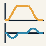
On a graph of Φ against t, the EMF is −N times the slope: negative on a rise, zero on any flat stretch however high it lies, positive on a fall. The steepest point of the rise, near 2.2 s, has a slope of about 0.45 mWb/s, and 200⋅0.45≈89mV is the peak reading.
Common mistakes
A strong field is not a large EMF. With the magnet resting inside, 0.20 mWb threads every turn and the EMF is exactly zero.
The induced current opposes the change, not the field. As the magnet leaves, the induced field points the same way as the magnet's own field, propping up the falling flux.
The angle θ is measured from the normal, not from the plane. A coil whose plane makes 30° with the field has θ=60∘, so with the animation's numbers Φ=BAcos60∘=0.10mWb, not 0.17 mWb.
Keep the factor N and convert with 1cm2=10−4m2. Dropping N turns the animation's 20 mV average into 0.1 mV; taking 10 cm² as 10−2m2 turns it into 200 mV.
An EMF is not a current. A coil with open ends has the full EMF across them but carries no current, so it feels no braking at all.
Where you meet it
Most of the world's electricity comes from generators that turn magnets past coils to make alternating current at 50 or 60 Hz. Transformers change voltages by induction, wireless phone chargers pass energy across a gap at about 100–200 kHz, induction hobs heat a pan through eddy currents, and guitar pickups and metal detectors sense moving or hidden metal. Some trains brake with eddy currents, and electric cars recover energy by running their motors as generators.
The machines are the subject of Motors, Generators and Transformers. Faraday's law is also half of the mechanism of light: changing magnetic and electric fields make each other and travel together as Electromagnetic Waves.
Advanced
Key ideas
∇×E=−∂B/∂t: a changing B creates a curling, non-conservative E that drives charges round a still circuit.
The pulse area ∫εdt=−NΔΦ is fixed by the flux change; the charge moved is Q=N∣ΔΦ∣/R, whatever the speed.
In a moving conductor the EMF is the magnetic force on its charges: ε=∮(v×B)⋅dl=BLv for a rod on rails.
With sliding contacts (Faraday's disc) the flux rule can fail; ε=∮(E+v×B)⋅dl always holds.
A coil spinning in a uniform field gives ε=NBAωsinωt: zero when the flux is largest, peak when it is zero.
EMF and flux, defined precisely
Faraday's law links two quantities, the EMF round a circuit and the magnetic flux through it, so both need exact definitions before the law can be stated. Walk once round a closed path C in small steps dl. The EMF ε of the path is the work done per unit charge, over that one trip, by whatever pushes the charge along. If a charge q feels the force F, then ε=∮(F/q)⋅dl
An EMF is not a potential difference. The electric field of charges at rest does no net work on a charge taken round a closed loop, because the charge ends at the potential it started from: that field has zero circulation. So whenever a closed path has an EMF, some other push is at work, and this lesson is about where that push comes from.
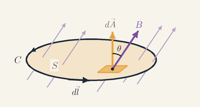
Figure 1. A closed path C bounds a surface S in a field B. Notice the small patch dA at the angle θ to B: it points the way the right thumb does when the fingers follow the step dl. Not to scale.Legend
C
The closed path, here the circuit, walked in small steps.
S
A surface whose rim is C; every such surface carries the same flux.
dl
One small step along C, in the sense shown by the arrowheads.
m
dA
A small patch of S as a vector: its length is the area of the patch, it is perpendicular to the patch, and the right-hand rule picks its side.
m2
B
Magnetic field at the patch.
T
θ
Angle between B and dA.
rad
Figure 1 sets up the geometry. The arrowheads on C give the sense in which the path is walked, and one step dl is drawn. To measure the flux we need a surface S whose rim is C; the figure uses the flat one. Cut S into small patches and describe each patch by a vector dA: its length is the area of the patch, and it stands at right angles to the patch. A patch has two sides, and the right-hand rule picks one: curl the fingers of the right hand along dl, and the thumb gives the direction of dA. This rule ties the sign of the flux to the sense in which the EMF is counted.
Now look at the patch itself. The field B there makes the angle θ with dA, so only its component Bcosθ crosses the patch, and the patch adds BdAcosθ=B⋅dA to the flux. Adding up all the patches gives the flux through C: Φ=∫B⋅dA Why does the choice of surface not matter? Because ∇⋅B=0: field lines never start or end, so every line that crosses the flat surface also crosses a dome standing on the same rim. Every surface bounded by C carries the same flux, so Φ belongs to the path itself.
With both quantities defined, Faraday's law says that the EMF is minus the rate of change of the flux. For a path at rest the only push is the electric field, and the law reads ∮E⋅dl=−dtd∫B⋅dA A coil of N turns is N such paths in series, each threaded by the same flux, so its EMF is ε=−NdtdΦ The minus sign is Lenz's law. A positive EMF drives current along dl, and by the right-hand rule the field of that current threads S along dA, adding positive flux. A rising flux therefore gets a negative EMF, whose current removes flux and so opposes the rise.
Stokes's theorem turns the circulation of E round C into the flux of ∇×E through S. Since the law holds for every loop, however small, it holds point by point: ∇×E=−∂B/∂t A changing magnetic field is surrounded by a curling electric field, whether or not a wire is there to feel it.
Motional EMF: a circuit moving in a steady field
The flux through a circuit can change for two quite different reasons: the circuit moves through a field that stays put, or the field changes while the circuit stays put. Faraday's law covers both with one formula, but the physics behind them differs. Take the moving circuit first, because there the law follows from a force you already know.
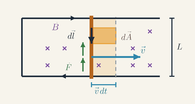
Figure 2. A rod slides at velocity v along rails in a field B into the page. In the time dt its element dl sweeps the shaded strip dA, and the force F on its charges points against dl. Not to scale: vdt is drawn far too large.Legend
B
Magnetic field, pointing into the page (the crosses).
T
v
Velocity of the rod, to the right.
m/s
L
Length of the rod between the rails.
m
vdt
How far the rod moves in the short time dt.
m
dl
A small element of the rod, pointing in the sense of the circuit: clockwise, so down the rod.
m
dA
The strip swept by dl in the time dt, as an area vector vdt×dl; it points into the page.
m2
F
Magnetic force qv×B on a positive charge q moving with the rod; it points up the rod.
N
Figure 2 shows the simplest moving circuit. A rod of length L lies across two rails joined at the left end, and it slides to the right with velocity v. The field B points into the page everywhere (the crosses). The charges in the rod move with it, so each feels the magnetic force qv×B; for a positive charge this is the force F, which points up the rod. The EMF is the work per unit charge of this force round the circuit: ε=∮(v×B)⋅dl Only the rod moves, so only the rod contributes. Along it v×B has the size vB and points along the rod, so the size of the EMF is BLv.
Now connect this to the flux. In the short time dt the element dl moves through vdt and sweeps out the shaded strip, whose area vector is dA=vdt×dl; the whole rod sweeps the area Lvdt. Because ∇⋅B=0, the flux through the circuit grows by exactly the flux through these swept strips. Dividing by dt: dtdΦ=∮B⋅(v×dl)=−∮(v×B)⋅dl The second step uses the cyclic property of the triple product, B⋅(v×dl)=dl⋅(B×v), together with B×v=−v×B. The right-hand side is minus the EMF, so ε=−dΦ/dt. For a circuit moving through a fixed field, the flux rule is not a new law: it is a consequence of the magnetic force on moving charges.
The signs in Figure 2 bear this out. The element dl points down the rod, in the sense of travel round the circuit, which is clockwise. By the right-hand rule dA then points into the page, along B, so the flux is positive and growing. The force F points up the rod, against dl, so the EMF is negative: a rising flux and a negative EMF, as Lenz's law requires.
A changing field: the induced electric field
Now hold the circuit still and change the field instead, for example by moving the magnet rather than the coil. Charges at rest feel no magnetic force, so the magnetic force cannot be the push. The push comes from a genuinely new electric field, one whose curl is not zero: ∇×E=−∂B/∂t. Nothing in the magnetic force law predicts it. It is a separate law of nature, found by experiment.
Yet the two mechanisms always give the same EMF, so only the relative motion of magnet and coil matters. Einstein's 1905 relativity paper opens with exactly this example. In the frame of the magnet, the charges in the coil move and feel the force qv×B; in the frame of the coil, they are at rest and feel qE. Relativity shows that these are one field seen from two frames: how it splits into electric and magnetic parts depends on the observer.
The EMF pulse: its height and its area
When the animation's magnet is pushed into the coil, the EMF arrives as a single pulse. Two features of the pulse carry the physics: its height is set by how fast the flux changes, and its area by how much the flux changes in total.
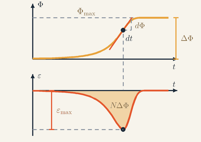
Figure 3. The flux Φ(t) as the animation's magnet enters the coil, with the EMF ε=−NdΦ/dt below it. The steepest point of Φ sits straight above the bottom of the pulse, and the shaded area of the pulse is NΔΦ.Legend
t
Time.
s
Φ
Flux through one turn of the coil.
Wb
Φmax
The largest flux, reached once the magnet rests inside the coil.
Wb
ΔΦ
Total rise of the flux during the push.
Wb
dt
A short time interval: the horizontal leg of the slope triangle.
s
dΦ
Change of Φ along the tangent during dt: the vertical leg.
Wb
ε
EMF induced in the whole coil of N turns.
V
εmax
Depth of the pulse, below the steepest point of Φ; the EMF itself is negative there.
V
NΔΦ
Size of the shaded area under the pulse: N turns times the rise ΔΦ.
V⋅s
Figure 3 is drawn from the same model as the animation. The upper graph is the flux Φ(t) through one turn while the magnet is pushed in: it rises by ΔΦ to Φmax and then stays flat. The lower graph is the EMF ε(t), which by Faraday's law is −N times the slope of the upper graph. Look at the dot on the flux curve: there the tangent is steepest, and its slope triangle has the legs dt and dΦ. Follow the dashed line straight down, and the EMF is at the bottom of its pulse, whose depth is εmax. Where Φ is flat, before the magnet arrives and after it comes to rest inside, the EMF is zero, however large the flux.
Start with the height. In the model, the flux through a turn depends on the distance s between the centres of magnet and coil as Φ(s)=Φmax[1+(s/a)2]−3/2 with Φmax=0.20mWb and a=30mm. The flux depends on time only through s, so the chain rule splits the EMF into a factor set by the shape of the field and a factor set by the speed: ε=−NdsdΦdtds The slope dΦ/ds is proportional to (s/a)[1+(s/a)2]−5/2. Setting the derivative of this to zero gives 1+(s/a)2=5(s/a)2, so the slope is steepest at s=±a/2, where its size is 0.86Φmax/a. While entering, the magnet moves at a steady 78 mm/s, and it passes s=−15mm at t≈2.2s. The depth of the pulse is therefore εmax=200⋅0.86⋅(0.20×10−3/0.030)⋅0.078≈0.089V which is the −89mV trough of the graph. The pulse is sharp: it is deeper than half this value for only 0.37 s of the 2 s push.
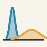
Now the area. Integrating Faraday's law over the whole pulse gives ∫εdt=−N∫dΦ=−NΔΦ The area depends only on the total change of flux, not on how quickly it happened. Here the flux rises from 0.0025 mWb, with the magnet 125 mm away, to 0.20 mWb, so the area is −200⋅(0.20−0.0025)mWb≈−39.5mV⋅s (a volt-second is a weber). Pulling the magnet out gives a pulse of the same area and the opposite sign. A push twice as fast gives a pulse twice as tall and half as wide, with the same area.
The area has a practical use. Through a circuit of resistance R the charge that flows is Q=∫εdt/R, so Q=N∣ΔΦ∣/R: about 2.0 mC per pulse with 20 Ω. This stays exact even when the coil's own inductance matters, because the current is zero before and after the pulse, so the inductive EMF integrates to zero. A search coil connected to a charge meter can therefore measure a field whatever the speed of the hand that moves it.
The rotating coil: a generator
A generator changes the flux by rotation: a coil turns steadily in a fixed field. Let it turn at angular speed ω in a uniform field B, so that the angle θ of Figure 1, between B and the coil's area vector, grows as θ=ωt. Each turn, of area A, then carries Φ=BAcosωt, and Faraday's law gives ε=−NdtdΦ=NBAωsinωt The EMF is zero when the coil faces the field square on and the flux is largest, because the cosine is flat at its peak. The EMF is largest a quarter turn later, when the coil lies edge-on to the field and the flux passes through zero, changing fastest. Flux and EMF are a quarter cycle apart, like position and velocity in simple harmonic motion.
Spin the animation's coil, with N=200 and A=1.0×10⁻³m2, in its 0.20 T field 50 times a second, so that ω=2π⋅50≈314rad/s. The peak EMF is NBAω=200⋅0.20⋅1.0×10−3⋅314≈12.6V The average form of the law checks this. In each half turn the flux goes from +0.20 to −0.20mWb in 0.010 s, so the average EMF is 200⋅0.40×10−3/0.010=8.0V. That is 2/π of the peak, the mean value of a half sine wave, as it should be. The peak is 140 times the 89 mV of the hand-pushed magnet, for two reasons: the flux now reverses completely instead of merely appearing, and it does so a hundred times a second.
Induced currents push back
Once an induced EMF drives a current, that current sits in a magnetic field and feels a force. By Lenz's law the force always opposes the motion that caused it, so induction acts as a brake. The rod on rails makes this quantitative.
Push the rod and let go. At speed v the EMF BLv drives the current I=BLv/R through the circuit's resistance R, and the field pushes back on the rod with the force BIL=B2L2v/R. Newton's second law for a rod of mass m is then mdtdv=−RB2L2v The drag is proportional to the speed, so the speed decays exponentially, v=v0e−t/τ, with the time constant τ=mR/(B2L2).
Take the rails of the Intermediate example, with B=0.40T, L=0.25m and R=0.50Ω, and a 20 g rod: τ=0.020⋅0.50/(0.402⋅0.252)=1.0s. Launched at 2.0 m/s, the rod coasts a distance v0τ=2.0m (the integral of v over all time), and all of its 0.040 J of kinetic energy ends up as heat in the resistor.
In solid metal there is no wire to guide the current: the induced electric field drives eddy currents round closed loops inside the metal itself. They heat the pan on an induction hob, brake trains without wear and make a magnet sink slowly down a copper tube. Transformer cores are built from thin insulated sheets, called laminations, which break these loops and cut the losses. A coil also opposes changes in its own current, because the flux of that current threads the coil itself. This self-induction is why breaking the current in a large coil can draw a spark.
Worked problem: a magnet dropped through the coil
Drop the animation's magnet from rest, axis vertical, with its centre 20 cm above the centre of the coil, so that it falls straight through. First leave the coil open: no current flows, so nothing brakes the fall. How do the entry and exit pulses compare? Then close the coil through 20 Ω: how much braking does that add?
Peak heights. Each pulse is deepest where the slope dΦ/ds is steepest, at s=±15mm, so ∣εmax∣≈N⋅0.86(Φmax/a)v=200⋅0.86⋅(0.20×10−3/0.030)v≈1.15v in volts for v in m/s. The centre of the magnet reaches s=−15mm after falling 0.185 m, at v=2⋅9.81⋅0.185≈1.91m/s, and s=+15mm after 0.215 m, at about 2.05 m/s. So the entry pulse peaks near −2.2V and the exit pulse near +2.35V, only 15 ms later.
Widths. Each pulse has the area NΦmax≈40mV⋅s, because the flux rises from almost nothing to Φmax and then falls back. With equal areas, the taller exit pulse must be narrower: area divided by height gives about 18 ms for the entry pulse and 17 ms for the exit pulse. Both pulses are about 25 times taller and 25 times narrower than in the animation, the ratio of the speeds.
Braking. Now close the coil through 20 Ω. The power turned into heat is ε2/R, and its integral ∫ε2dt/R, worked out numerically over both pulses, is about 5.8 mJ. A 50 g magnet arrives with mgh=0.050⋅9.81⋅0.20≈0.098J of kinetic energy, so it loses about 6% of its energy. Its speed goes as the square root of the energy, so it drops by only about 3%: ignoring the braking in the first part was fair. In a copper tube the resistance is tiny, the currents are large, and the braking is strong enough to hold the magnet to a slow terminal speed.
Limits of validity: when the flux rule fails
The flux rule works when the path of the current moves with the material that carries it, as the rod on rails does. A spinning disc shows what goes wrong when it does not, and what to use instead.
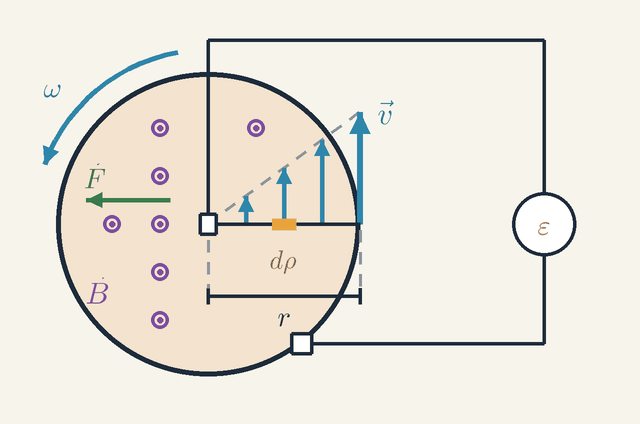
Figure 4. A copper disc turns at ω in a field B out of the page, with brushes on the axle and the rim. The velocity v grows with the distance from the axle, so a piece dρ of the radius adds more EMF the farther out it lies. Not to scale.Legend
B
Magnetic field along the axle, pointing out of the page (the dots).
T
ω
Angular speed of the disc.
rad/s
r
Radius of the disc: the distance from the axle to the rim.
m
dρ
A short piece of the radius, at distance ρ from the axle.
m
v
Velocity of the metal at a point of the radius, of size ωρ: it grows in proportion to the distance from the axle.
m/s
F
Magnetic force qv×B on a positive charge in the metal: along the radius, away from the axle.
N
ε
EMF between the brushes, read by the meter.
V
Figure 4 shows a copper disc of radius r turning at angular speed ω in a field B along its axle, out of the page (the dots). One brush touches the axle and one the rim, and wires lead from both to a meter that reads the EMF ε. The current runs through the wires, the meter and one radius of the disc between the brushes. That path stays where it is as the disc turns, so the flux through it never changes, and the flux rule predicts no EMF at all. Yet the meter reads one.
The force law explains the reading. The metal of the disc moves, so the charges in it feel qv×B. At distance ρ from the axle the metal moves at the speed ωρ, so in Figure 4 the arrows v along the radius grow in proportion to ρ, and their tips lie on a straight dashed line through the centre. The force F on a positive charge points along the radius, away from the axle (it is drawn on the left-hand radius). A short piece dρ of the radius therefore adds Bωρdρ to the EMF, and the sum from the axle to the rim is the area under that straight line, a triangle: ε=∫0rBωρdρ=21Bωr2 For a disc of radius 10 cm turning 50 times a second in 0.50 T this is 0.79 V. The rule that never fails is the force law itself, with the force per unit charge integrated along the actual path of the charges: ε=∮(E+v×B)⋅dl
The circuit picture has limits of its own. It assumes the EMF appears all round the loop at once, which needs a circuit much smaller than the wavelength c/f of the changing field: 6000 km at 50 Hz, but only 30 cm at 1 GHz, where wires start to radiate as aerials. We have also ignored the coil's own field. For the animation's coil, of length ℓ=60mm, the long-solenoid estimate of its inductance, μ0N2A/ℓ, gives under 1 mH, and with 20 Ω a time constant near 40 µs: negligible against the 0.4 s pulse, but dominant at high frequencies.
How the push splits between E and v×B depends on the frame of reference. At low speeds, a frame moving at velocity v sees the electric field E′=E+v×B; at the 78 mm/s of the animation this rule is off by only about (v/c)2≈7×10−20.
At the other extreme is a superconducting ring. Round a loop with zero resistance the total EMF must be zero, or the current would grow without limit, so the flux through the ring, including the flux of its own current, cannot change at all. That flux also comes only in whole multiples of the flux quantum h/2e≈2.07×10−15Wb. The coil's 0.20 mWb is about 1011 quanta; SQUIDs, superconducting quantum interference devices, resolve a small fraction of one quantum, enough to record the magnetic fields of the brain.
Where this leads
Magnetic Force on Moving Charges supplied the v×B half of this lesson. Motors, Generators and Transformers applies the law to machines: a transformer is two coils sharing one changing flux, and a motor is a generator run backwards, with the back EMF that Lenz's law predicts. Electric Power and Energy at Home follows that energy to the socket, and the eddy-current brake reappears as a linear damper in Damping and Resonance.
Add Maxwell's correction, that a changing electric field also makes a magnetic field, and the two fields regenerate each other in empty space, travelling at c=1/μ0ε0: the subject of Electromagnetic Waves. And because only the relative motion of magnet and coil matters, the road leads on to Special Relativity.
Key formulas
Magnetic flux through a flat loop
Φ=BAcosθ
Flux measures how much magnetic field passes through a loop: the field times the area, reduced by cosθ when the field is tilted. Only the component of the field along the normal crosses the loop; the component lying in its plane slides past. The sign depends on which side of the loop is taken as positive, and it flips when the field reverses or the loop turns over.
Symbols
Φ
flux through the loop
Wb
B
magnetic field, uniform over the loop
T
A
area of the loop
m2
θ
angle between the field and the normal to the loop
rad
When it holds: For a flat loop in a uniform field. Otherwise add up the field over the surface, Φ=∫B⋅dA; for a coil of N turns, multiply by N to get the flux linkage.
Example: The animation's coil, with B=0.20T along its axis and A=10cm2: Φ=0.20⋅1.0×10−3=2.0×10⁻⁴Wb=0.20mWb.
Faraday's law: average EMF
ε=−ΔtNΔΦ
The EMF induced in a coil equals the number of turns times the rate at which the flux through each turn changes. Over a finite interval the formula gives the average EMF. The minus sign is Lenz's law: the EMF drives a current whose own field opposes the change. A constant flux gives zero, however large it is.
Symbols
ε
average induced EMF
V
N
number of turns
ΔΦ
change of flux through one turn
Wb
Δt
duration of the change
s
When it holds: Gives the average over Δt; the EMF at an instant is −NdΦ/dt. It assumes that every turn has the same flux and that the path of the current moves with the conducting material, as it does for a rod on rails.
Example: The animation's push: 200⋅0.20×10−3/2.0=0.020V, or 20 mV on average, while the readout peaks near 89 mV.
Faraday's law: EMF at an instant
ε=−dtNdΦ
Letting Δt shrink to zero gives the EMF at each instant: −N times the slope of the Φ(t) graph. Steep stretches give large EMFs and flat stretches none. Integrated over time, the area under an EMF pulse is −NΔΦ, however fast the change happened.
Symbols
ε
EMF at time t
V
N
number of turns
Φ
flux through one turn
Wb
t
time
s
When it holds: Holds whenever the path of the current moves with the conducting material, whether the field changes or the circuit moves. When material slides across a path that stays put, as in a spinning disc with brushes, use the force law ε=∮(E+v×B)⋅dl instead.
Example: The steepest slope of the animation's flux, about 0.45 mWb/s, gives 200⋅0.45≈89mV, the peak reading.
Motional EMF of a sliding rod
ε=BLv
A rod moving across a field carries its charges with it, and the magnetic force qvB pushes them along the rod. The work per unit charge over the length L is BLv. Faraday's law gives the same result, because the rod sweeps out area at the rate Lv.
Symbols
ε
EMF between the ends of the rod
V
B
magnetic field
T
L
length of the rod across the field
m
v
speed of the rod
m/s
When it holds: When the rod, its velocity and the field are at right angles to one another and the field is uniform. Otherwise only the perpendicular components count: ε=∫(v×B)⋅dl along the rod.
Example: A 25 cm rod at 2.0 m/s in 0.40 T: ε=0.40⋅0.25⋅2.0=0.20V.
EMF of a coil rotating in a uniform field
ε=NBAωsinωt
A coil turning at angular speed ω has a flux BAcosωt through each turn, and −NdΦ/dt gives a sinusoidal EMF of amplitude NBAω. The EMF is zero when the coil faces the field, where the flux is largest, and peaks a quarter turn later, when the flux passes through zero. Turning twice as fast doubles both the amplitude and the frequency.
Symbols
ε
EMF at time t
V
N
number of turns
B
magnetic field, uniform
T
A
area of one turn
m2
ω
angular speed of the coil
rad/s
t
time since the coil faced the field
s
When it holds: For a uniform field and a constant angular speed, with t=0 when the coil faces the field. Real generators shape the field and use several coils, but the amplitude still grows in proportion to ω.
Example: The animation's coil turned 50 times a second (ω≈314rad/s): ε0=200⋅0.20⋅1.0×10−3⋅314≈12.6V.
Faraday's law in integral form
∮E⋅dl=−dtd∫B⋅dA
The tangential electric field, added up once round any closed path, equals minus the time derivative of the magnetic flux across any surface whose edge is that path. A changing magnetic field is therefore surrounded by a curling electric field, even in empty space, and this field drives charges round a circuit at rest. By Stokes's theorem it is equivalent to ∇×E=−∂B/∂t.
Symbols
E
electric field
V/m
dl
element of the closed path
m
B
magnetic field
T
dA
element of a surface bounded by the path, normal given by the right-hand rule
m2
t
time
s
When it holds: Exact for a path fixed in space: it is one of Maxwell's equations. For a moving circuit the EMF also includes ∮(v×B)⋅dl.
Example: Inside a wide solenoid whose field rises at 0.50 T/s, a coaxial circle of radius r=10cm has 2πrE=πr2dB/dt, so E=(r/2)dB/dt=0.025V/m.
Glossary
Electromagnetic induction
The production of an EMF, and so of a current in a closed circuit, by a changing magnetic flux. A constant flux, however large, induces nothing; Michael Faraday discovered the effect in 1831.
Magnetic flux
The amount of magnetic field threading a surface, Φ=∫B⋅dA; for a flat loop in a uniform field, BAcosθ. It is not the field itself: a weak field over a large loop can give more flux than a strong field over a small one.
Flux linkage
The flux through one turn times the number of turns, NΦ, when every turn carries the same flux. The EMF is minus its rate of change; in the animation it reaches 200⋅0.20mWb=40mWb.
Electromotive force (EMF)
The work done per unit charge on charges taken once round a circuit, measured in volts. Despite its name it is not a force, and unlike a potential difference it can be non-zero round a closed loop.
Faraday's law of induction
The EMF round a circuit equals minus the rate of change of the flux linkage, ε=−NdΦ/dt. It applies equally when the field varies and when the circuit moves or deforms.
Lenz's law
The induced current flows so as to oppose the change of flux that causes it; it is the minus sign in Faraday's law. It opposes the change, not the field, and it expresses energy conservation.
Motional EMF
The EMF in a conductor moving through a magnetic field, due to the magnetic force qv×B on its charges. For a rod of length L moving at speed v across a field B, ε=BLv.
Induced electric field
The electric field that surrounds a changing magnetic field, obeying ∇×E=−∂B/∂t. Its field lines close on themselves, so it is not the gradient of any potential and can drive charges round a loop.
Eddy currents
Currents induced round closed loops inside a solid conductor by a changing or moving field. They heat the metal, as in induction hobs, and brake its motion; thin insulated sheets keep them small in transformer cores.
Generator
A machine that turns mechanical work into electrical energy by induction, usually by rotating coils and magnets past each other. A coil spinning at ω in a uniform field gives the alternating EMF NBAωsinωt.
Self-induction
The EMF induced in a coil by changes of its own current, which change its own flux. By Lenz's law it opposes the change of current; the coil's inductance measures its strength.
Faraday disc
A metal disc spinning in a field parallel to its axle, with sliding contacts on the axle and the rim. It gives a steady EMF 21Bωr2 although the flux through the current's path never changes: a case where the flux rule fails and the force law must be used.
Quantities
Φ
Magnetic flux
Wb
The flux through one turn of the coil, with 1Wb=1T⋅m2. In the animation it rises from almost zero to 0.20 mWb as the magnet enters.
ΔΦ
Change of flux
Wb
Final minus initial flux through one turn over the interval considered. It alone fixes the area of an EMF pulse, −NΔΦ.
B
Magnetic field
T
The strength of the magnetic field, also called the magnetic flux density: the flux per square metre of a surface perpendicular to it. The magnet's field inside the coil is 0.20 T.
N
Number of turns
How many times the wire goes round the coil. Each turn adds the same EMF, so the total is N times that of one turn; the animation's coil has 200.
ε
Electromotive force (EMF)
V
The induced EMF round the circuit; its sign, relative to the chosen positive direction, tells which way it drives current. It peaks at about 89 mV in the animation.
Δt
Time interval
s
The time over which the flux changes; Faraday's law with a finite interval gives the average EMF over it.
L
Length of the rod
m
The length of the moving conductor that lies across the field, for example the part of a rod between two rails.
v
Speed of the rod
m/s
The speed of the conductor across the field, at right angles to both the rod and the field.
ω
Angular speed
rad/s
How fast the generator coil turns, ω=2πf: 50 turns per second is about 314 rad/s.
E
Induced electric field
V/m
The electric field around a changing magnetic field; its circulation round a closed path is the EMF of that path.
Quiz
Beginner A magnet rests inside a coil that is connected to a current meter. What does the meter show?
A large steady current
Zero current
A current that keeps growing
A current that flips back and forth
Show answer
Answer: B. Zero current
A current is induced only while the magnetism through the coil changes. A magnet at rest, however strong, induces nothing.
Beginner Which of these makes the meter needle swing further?
Moving the magnet in faster
Moving the magnet in more slowly
Holding the magnet still inside the coil
Using a coil with fewer turns
Show answer
Answer: A. Moving the magnet in faster
A faster change gives a bigger induced current. More turns and a stronger magnet help too; holding the magnet still gives none.
Beginner You push a magnet into a coil and the meter needle swings left. What happens when you pull the magnet out?
It swings left again
It does not move
It swings right
It swings left and stays there
Show answer
Answer: C. It swings right
Pulling the magnet out changes the magnetism in the opposite direction, so the current, and the needle, reverse.
Intermediate The flux through a 100-turn coil changes from 0 to 2.0 mWb in 0.10 s. What is the average induced EMF?
0.02 V
0.2 V
2.0 V
20 V
Show answer
Answer: C. 2.0 V
|ε| = N·ΔΦ/Δt = 100 × 2.0 × 10⁻³ / 0.10 = 2.0 V. Forgetting the factor N gives 0.02 V.
Intermediate The north pole of a magnet is pushed towards a coil. By Lenz's law, the end of the coil facing the magnet becomes:
A north pole, repelling the magnet
A south pole, attracting the magnet
Non-magnetic
A north pole, attracting the magnet
Show answer
Answer: A. A north pole, repelling the magnet
The induced current opposes the change: to resist the approaching north pole, the coil makes a north pole that repels it.
Intermediate A flat coil of area 0.02 m² is perpendicular to a 0.5 T field. What is the flux through each turn?
Advanced A generator coil rotates in a uniform field. At the instant the flux through it is at its maximum, the induced EMF is:
Also at its maximum
Half its peak value
At its peak, but reversed in sign
Zero
Show answer
Answer: D. Zero
ε = −N·dΦ/dt depends on how fast Φ changes, not on its size. Φ = B·A·cos ωt peaks when the coil's plane is perpendicular to the field (ωt = 0), exactly where its slope, like sin ωt, is zero. The EMF is largest a quarter turn later, when the flux through the coil is zero.
Advanced A magnet is pushed into the same coil twice, once slowly and once quickly. How do the time integrals ∫ε dt of the two pulses compare?
They are equal, both −N·ΔΦ
It is larger for the fast push
It is larger for the slow push
It is zero for both
Show answer
Answer: A. They are equal, both −N·ΔΦ
∫ε dt = −N·∫dΦ = −N·ΔΦ depends only on the initial and final flux. The fast push gives a taller, narrower pulse with the same area.
 Physics Tutor